HOW TO CONNECT SIMPLY YOUR HP 141T OR HP 182T TO A PC |
Revision 1: Nov 30th 2007. Added 2 protection diodes
January 1st 2008. Added new pictures
By Dominique F1FRV
The idea was found in QEX (november 2007, with a french designed hardware and software. Unfortunately, it was impossible to obtain precise and concrete information from the author about "how to use it simply". Hardware was not very complicated, even if using a not very common PIC for the 10 bits A/D conversion, but major inconveniences are the use of a serial port instead of an USB port, external supply, and the worse: more than 65 Mo of esoteric and exotic programmation softwares to download, install, and try to understand...
A new and if possible simpler solution was searched.
I found one.... Here is the basic design. This approach uses your PC sound card to digitalise the auxiliary vertical analog output of the spectrum analyser on at least 16 bits. The "Pen Lift" auxiliary output is used as trigger. Some other measuring equipments have similar outputs, originaly made for an X-Y plotter.
The software used here (free for non commercial applications), is the excellent SOUNDCARD OSCILLOSCOPE written by Christian Zeitnitz, available to download at : http://www.zeitnitz.de/Christian/Scope/Scope_en.html .
Minimum Hardware

This is the simpliest way to see something.
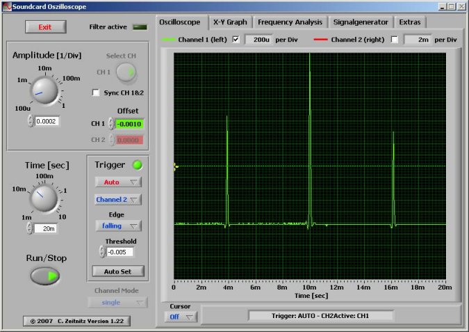
What the graph obtained is:
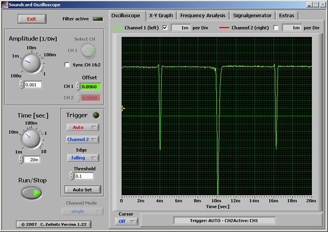
This is a picture of the 0 ray, at middle of the screen, 10 MHz/Div, with the 141T's internal marker 30 MHz@-30 dBm connected at input, but graph is inverted, not like on 141T screen...
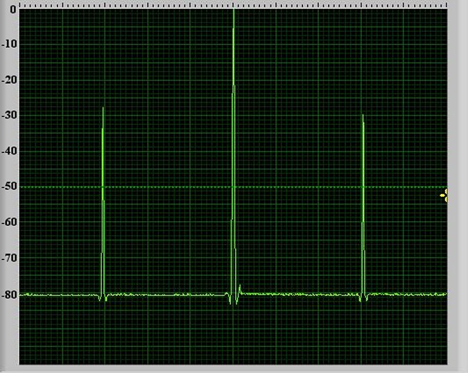
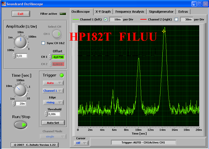
What the graph should be...
To capture screen pictures, you can use the very handy freeware MWSnap, available to download at: http://www.mirekw.com/winfreeware/index.html, or any other, among your favorite similar softwares.
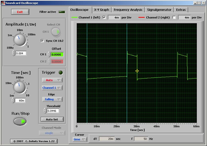
Synchro signal on a Sound Blaster PC128
Synchro signal on a C-media wave device
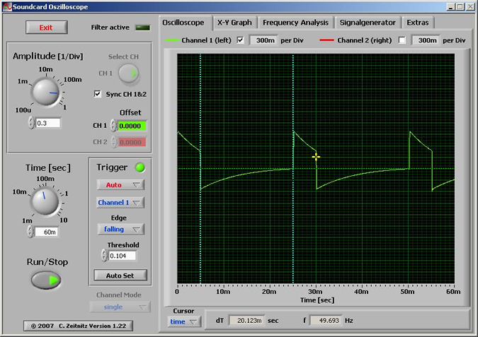
With different sound cards results can be slightly different.
Improved design
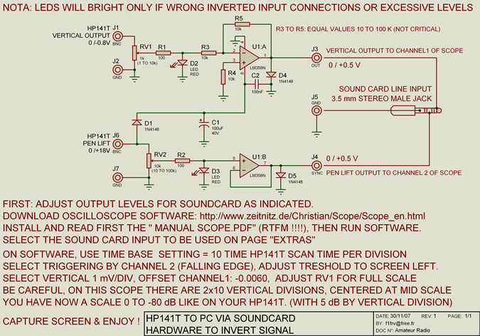
This design, very simple: no PIC, no supply, no hard to find parts. It is made for inversion of vertical output signal coming from the analyser (0 to -0.8 V), and convert it to 0 to +0.5 V. Protection of the sound card is made at two levels, at input and output of the op amp. If obtained levels are too low, replace the 1N4148's (output protection) by LED's.
Power supply is taken out of Pen Lift output 0 to +18 V pulses.
Use only LM358N op amps, as they include ground in their common mode range. Use shielded cables between interface and sound card, preferably with independant shielding for each wire to avoid "crosstalk".
Schematic design
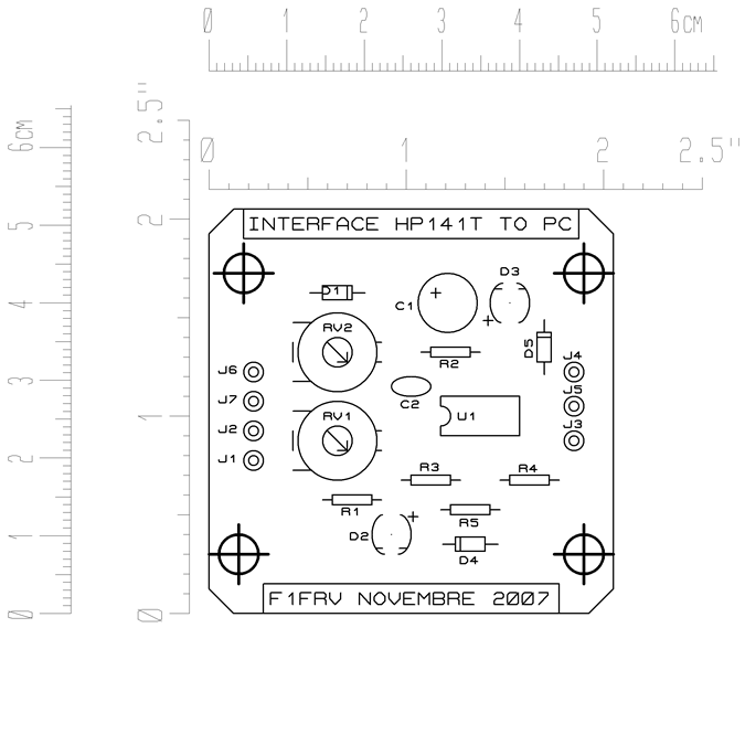
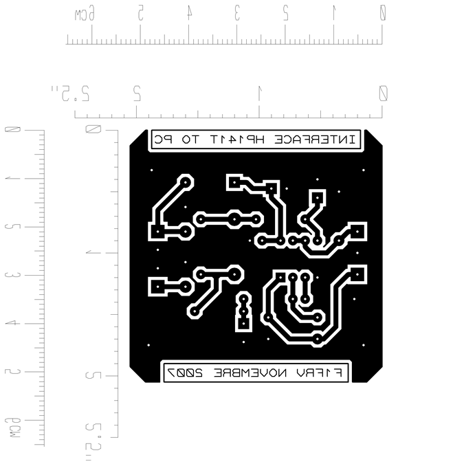
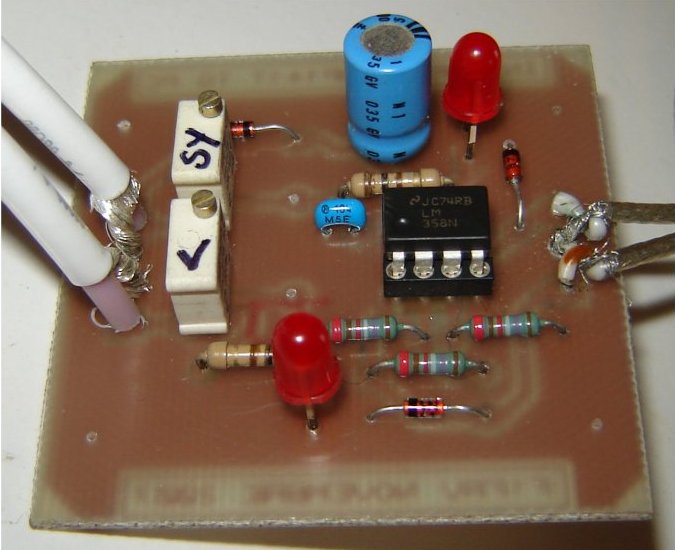
Layout and PCB
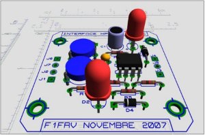
View & 3D simulations of the board
 Or
Or 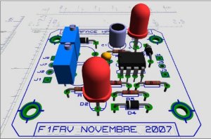
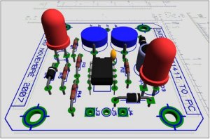 Or
Or 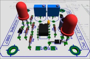
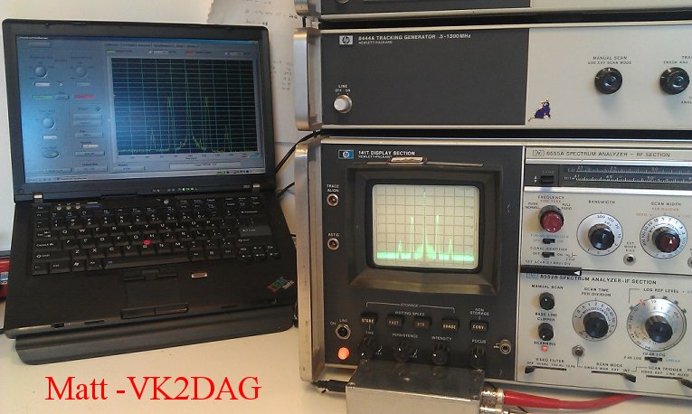
Results
Reference line -80 dB is now at lower part of the screen, like on spectrum analyser display. That's All Fox !!!!!!
You can download this page, and files necessary to make the PCB:
![]() Dominique - f1frv@sfr.fr
Dominique - f1frv@sfr.fr  OR
OR