Preparation of old tetrodes GU-43b, GU-78b, and similar, before use Revision 0: November 2006 |
![]() 03/2013: see at end of this page a simpler solution...
03/2013: see at end of this page a simpler solution...
by Dominique F1FRV & Roman US5WDX
Preparation of tubes which have not been used for years is necessary to avoid flashes inside the tube. All tubes have built in "GETTER", but, unfortunately for us, the GU-43b's & GU-78b's, and some similar tubes, do not have getters in classical meaning, and gettering functions in these tubes are performed by hot internal surface of the anode, heated by the electrons flow, which is forced by the applying of nominal operating voltages to heater, grids and anode.
Getter definition from Wikipedia, the free encyclopedia
To prevent any remaining gases from remaining in a free state in a vacuum tube, modern tubes are constructed with "getters", which are usually small, circular troughs filled with metals that oxidize quickly, barium being the most common. Once the tube envelope is evacuated and sealed, the getter is heated to a high temperature (usually by means of RF induction heating) causing the material to evaporate, absorbing/reacting with any residual gases and usually leaving a silver-colored metallic deposit on the inside of the envelope of the tube. If a tube develops a crack in the envelope, this deposit turns a white color when it reacts with atmospheric oxygen.Large transmitting and specialized tubes often use more exotic getters.
Getter: un article de Wikipédia, l'encyclopédie libre
"Getter" est un élément composant la plupart des tubes électroniques. Il évite l'apparition de gaz rémanents dans le tube. Les tubes modernes sont souvent équipés d'un getter de petite taille, généralement de forme circulaire, qui contient un métal qui s'oxyde rapidement ; le baryum est le plus courant. Une fois le vide effectué et l'enveloppe étanchéifiée, le getter est chauffé à haute température (souvent par induction avec des radiofréquences) ce qui provoque l'évaporation du métal contenu par le getter. Le métal absorbe alors les gaz résiduels en créant dans la plupart des cas un dépôt de couleur argentée sur l'enveloppe du tube. Si une fuite se développe sur le tube, le dépôt disparaît par réaction avec l'oxygène, laissant un dépôt blanc. Les tubes spécialisés et les tubes de fortes puissances utilisent souvent des getters plus exotiques.Power tubes with conventional getter can be simply prepared for use, in appliying heater voltage, with small air cooling on tube to evacuate heater calories. One day of heating by year of storage is an average for a gassy tube, and if you are lucky to find a tube with a good vacuum, one hour of heating per year of storage is sufficient . . .Tubes without conventional getter are more complex to prepair ... Here is a (not so) short description of the tubes conditioning process.
Procedure to be applied:
Step 1 / Heater voltage
Apply heater voltage only for ~ 12 to 24 hours (more for very old tubes). Use start-up inrush current limiting resistor during the first 15 seconds. Calculate resistor value for ~ heater nominal current on short circuit. Eg. for heater 12 V @ 6 Amps, resistor selected is 2.2 Ohms, 20 Watts.Check the heater voltage, and keep it at the lowest operating voltage given in the tube datasheet. At the end of this pre-heating period, maintain blower running at least 2 minutes after heater voltage removal.
Step 2: Check the vacuum of your tube.
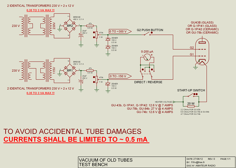
Apply: heater voltage, variable Ug1 voltage (0 to -150 Volts), and neither HV, nor G2 voltages (and obviously no RF). Control grid 1 measured reverse current should be less than 50 µA @ -100 Volts.Then, apply temporarely G2 variable voltage (0 to 300 Volts) with a push button, G1 reverse current should not increase, or at worse, no more than 25 %. There must be NO glitches during these operations.If current is much higher than 100 µA, be careful, vacuum is poor, or there is some other internal contamination, or grids displacement toward cathode due to manufacturing faults, cruel mishandling by the shipping service, or improper use by its previous owner ...If current is higher than 500 µA, do not loose precious time with this tube. Even with long time regeneration, it will never be safe to use, and most probably never able to accept full rated voltages, or overloads. This tube is good to be placed in a museum shelf ... (Except if you know an "expert" with good experience on gassy tubes regeneration). But this tube will certainly continue leaking and bringing you problems in use.
Schematic of hot-pot bench, heater and G1 current test.
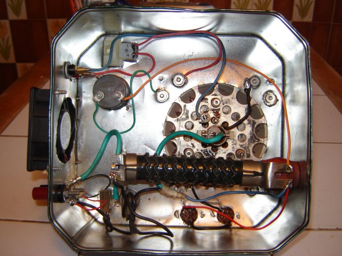
UGLY hot-pot bench, heater and G1 current test.With heater 0-15 V meter and grid1 0-200 µA meter.
Heater soft start-up with 2.2 Ohms resistor.
Small blower to evacuate heater calories
STRONG WARNING ! ! !
You are dealing with lethal voltages.
Be very careful during every operation, and remember about high energy stored in power supplies capacitors. If you are neither confident nor experienced enough, ask someone authorised and experienced.
Step 3a : If vacuum is poor Place the tube in the amplifier, with adequate air cooling blower running. Use a rotary variable transformer ("VARIAC") in the primary of your HV anode supply. Apply full heater and maximum grid 1 voltages. After this, apply ~50% of plate voltage through a serial 1000 Ohms (+/- 50%) 100 Watts resistor, and a fast 1-2 Amp fuse. Then, apply ~70% of G2 screen grid voltage through a serial 1000 Ohms (+/- 50%) 2 to 5 Watts resistor, and a fast 0.05-0.1 Amp fuse. There must be NO glitches during these operations.It is safe to have G2 and HV supplies shunting down together in case of problems, and manual restart with the right sequence: HV first, then G2.
Then, still with NO RF, slowly decrease G1 voltage, to run the tube on its iddle bias plate current, starting from 50 mA and going next to 100-150-200-250-300 mA, up to nominal idle current, in 15-30 minutes steps. If there is a glitch, repeat the step or even pull one back if flashing is too intensive, and if it stops glitching, go to the next one up. Surely, after 50% of nominal idle bias current, lower the serial resistor value in anode, because 1000 Ohms resistor will be too hot, so you go down to 500 Ohms, then 200 Ohms, just to keep them mildly warm, and leaving forever to 25-50 Ohms 50-200W to protect the tube against internal glitches in the future. All this will take at least 2-3 hours. When at nominal iddle current, maintain it for 2 to 12 hours, even more, if necessary, until the unwanted G1 leakage current decrease down to safe value (reverse current near to 0 µA. The lower the better ...).
If tube is too gassy, it will flash many times during its conditioning process. Every time the anode fuse will blow, and most of the times the screen fuse will too. Fast HV fuses are expensive and not always easy to find. Cheap, quick but still effective solution is a homebuilt fuse, made of a very thin wire (breaks at 1-2 A), soldered between two copper holders on a few centimetre piece of insulating material. Just remember to solder that wire about one cm above the surface of that insulator, so during the glitch the breaking wire will not burn it by the high temperature arc. When there is no fuse or no time to make one, unsolder the HV wire going from PS to the plate choke, bend it 2 cm away from its holder in HV safe direction, and make a 2 cm jumper made of copper wire of 0.05-0.1 mm of diameter. This simple fuse may save the tube during a strong glitch.
Step 3b: if vacuum is good
On the amplifier, with adequate air cooling blower running, apply 100% of heater, grid 1, plate HV and G2 screen voltages. Note: You MUST have in the +HV line a 25 to 50 Ohms permanently installed resistor of 50-200 W, and a temporary 200 ohm 100 W resistor to protect the tube against internal glitches. Fast fuses shall be also placed on HV & G2 lines.
Then, still with no RF, slowly decrease G1 voltage, to run the tube on its iddle bias plate current. Starting from 50 mA and going up 100-150-200-250-300 mA, up to nominal iddle current (200-300 mA for GU-43b, 400-600 mA for GU-78b), by 10-20 minutes steps. This test will take at least 1-2 hours. Fastest and most effective conditioning of the tube is when anode is very hot, typically when tube idle bias current reaches 50% of nominal operating value, and higher (at full HV). Do not exceed maximum plate power dissipation level, if you don’t want to kill the tube. When at nominal iddle current, and time and resources permit (electricity isn’t cheap), maintain heating of the anode for a few more hours. The longer the better...
Very often no glitches occurs during the whole conditioning process, everything goes smooth and quiet, but one have to be prepaired for a worse scenario. For example a short voltage spike in your AC supply network can make a good tube flash if it is not yet ready for say 50% voltage overload. But lets hope it doesn’t happen and we made it succesfully ....
Adequate cooling should be provided during the complete process, and should be kept running ~5 minutes after all voltages were removed.
Now: your tube is OK for RF !!!
If in a hurry, when there is no time to heat the tube under its nominal iddle current for another few hours, start a small RF drive, starting from 5 Watts and after few minutes slowly going up by increasing TRX output in 5 Watts increments. Be very careful each time to tune the amplifier correctly, because new untrained tubes, often do not tolerate big load mismatch , they may flash again... For that reason a good idea is to still keep 200 Ohms 100 W resistor in anode for the first hours of operating with RF, since the peak plate voltages now far exceeding the anode HV power supply voltage, and 200 Ohms is a bit more effective in glitch effects reduction than 25 or 50 Ohms. Of course with 200 Ohms you can not run PA at maximal power output, especially in RTTY, but i wouldn’t suggest doing this, with just installed tubes, untested yet by heavy load. Give them some time, in most cases few hours will be enough.
This is a very time and electricity consuming procedure, but it is done to provide a long and healthy life for the tube. After this procedure done, you will begin to love your GU-43b or GU-78b, sadly known as a big “glitchers”. It is so because in most cases people just didn’t took time to train them properly for 3-4 kV HV they put on them.
That's all fox !!!!
Thanks to Roman US5WDX
for his help.
These procedures were written, following the recommendations of the engineers working at the tube manufacturing companies LAMINA (now owned by Thomson), and POLYARON. Somewhat different, but similar in the idea, of other recommendations which can be found on other power tubes manufacturers documents, and other web resources...
In amateur and professional world is also known a much faster technique of high voltage inter-electrode burning process of cleaning internal contamination and high vacuum recovery. In general, it is done by applying current limited high voltages between tube electrodes, which are 3 to 10 times exceeding nominal operating values, so arc is appearing and burns inside. It can be done fast, but it is important to have a correct control on arcing, otherwise it can make more harm than good, so this process it is not described here, as extra equipment and knowledge are necessary.
You can download this page: Tetrode_Preparation.zip
Back to menu
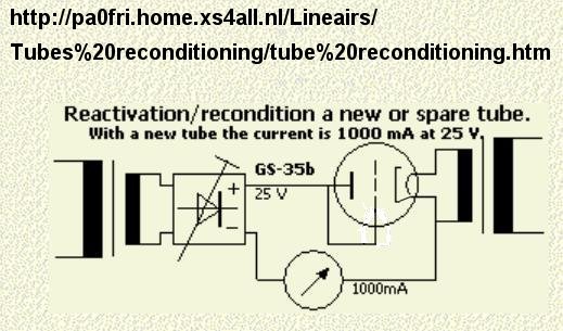
See also a simpler methodology at PA0FRI pages


 OR
OR