MODIFICATION OF R-140 LINEAR AMPLIFIER REPLACEMENT OF TETRODE GU-43b TO INCREASE POWER by F1FRV Rev 2d: June, 2007 |
Rev 2d: New pictures added
The idea was to increase the power of the amplifier. All internal components are oversized for amateur service, there are few things to do, to change this 1.5 to 2 liter class amp to a 3 to 5 liters amp class.
This has already been done, by some OM's or teams, in Austria, in St Petersbourg, in Czech republic, and certainly elsewhere ...
Amplifiers with variable capacitor at PI network output (olds "6LV's") are more easyly modified than models with 8 position swich for fixed values capacitors (new "6M1").
Original tube GU-43b or Q-1P/42 dissipation is 1 kW. The selected new tube dissipation is 2.5 kW.
The choice of tube was aimed by some guide lines: characteristic curves, input and output capacitances, who should be as similar as possible to those of GU-43b, dimensions, who shall not be too far from original tube, and availability at "reasonable" price of tubes and sockets.
Two tubes are here considered as possible substitutes: The GU-73b and the GU-78b. Both are able to work with plate voltage of +3000 V, screen supply of +350 V, and grid 1 voltage of -100 V, like original tube.
Original heater supply 12.6 Volts @ 7 Amps needs to be changed for a 27 Volts @ 5.5 Amps.
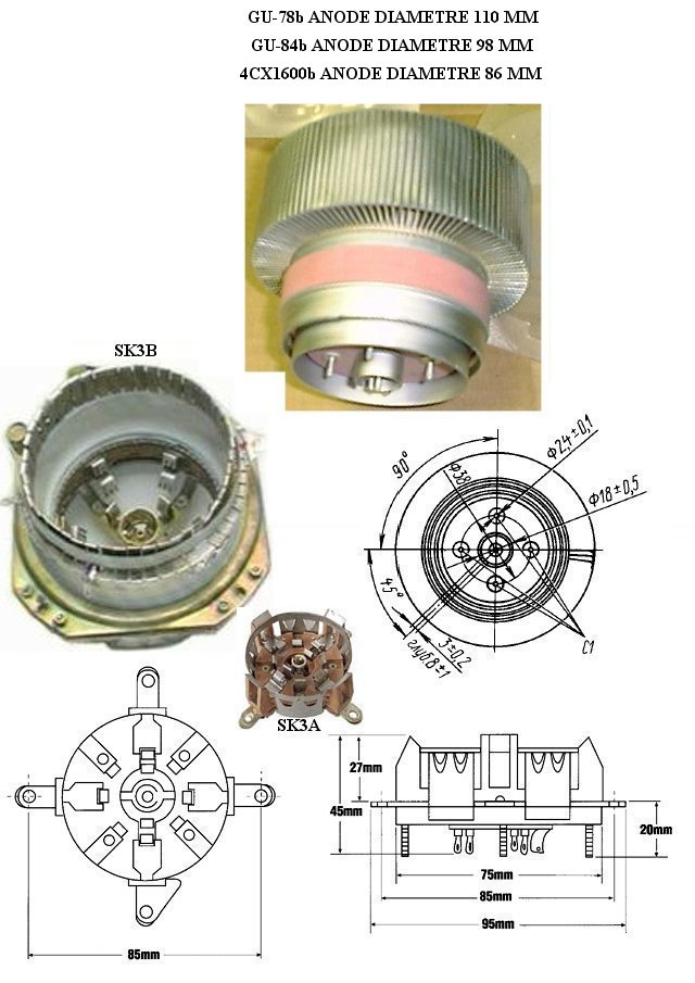
Sockets for the GU-78b are found more easily than those for GU-73b. They are similar (except anode diameter) to those used for the popular GU-84b and 4CX1600b. Several versions of the socket are available: SK3B, with ceramic/PTFE chimney, and SK3A without chimney (bad air cooling with this socket, avoid use).Some home made sockets can also be found on the market...
Be careful in purchasing socket with chimney, as diameter is 110 mm for GU-78b.
**************************************
An other tube could be considered as possible, and even better substitute: The GU-93b, with plate dissipation of 4 kW. Anode diametre is 115 mm, and weight ~ 3.5 kg. This tube can accept plate voltage of +3800 V (and more...), screen supply of +450 V. Heater power supply shall be 12 Amps @ 12.6 Volts.
Unfortunately, tubes and sockets are not easy to found...
**************************************
An other solution could be considered, and even the less expansive alternative: 2 x GU-43b in parallel.
Plate dissipation is 2 kW. Heater power supply shall be 15 Amps @ 12.6 Volts.
**************************************
Avoid sockets "SK3A": not enough space for cooling air to the tube !!!
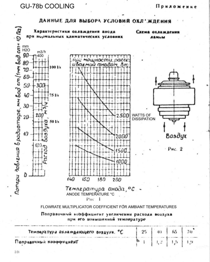
GU-78b Cooling curves (blower needs to be powerful...)
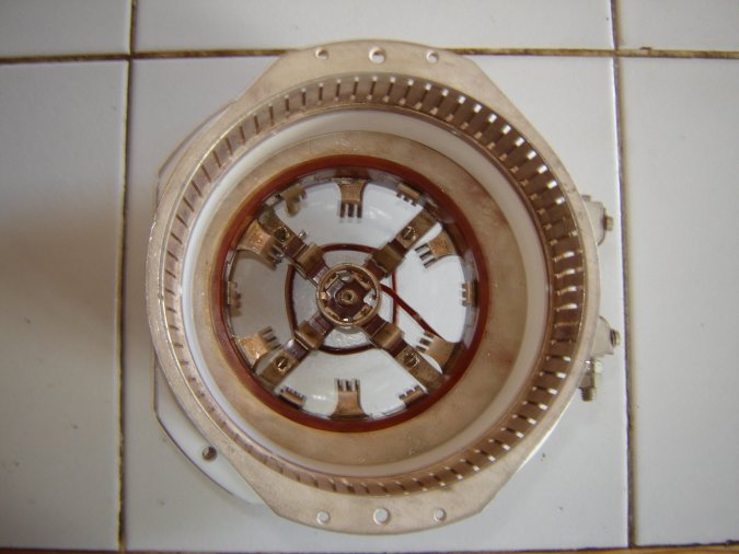
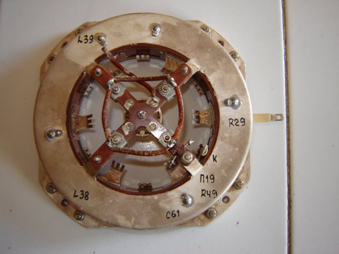
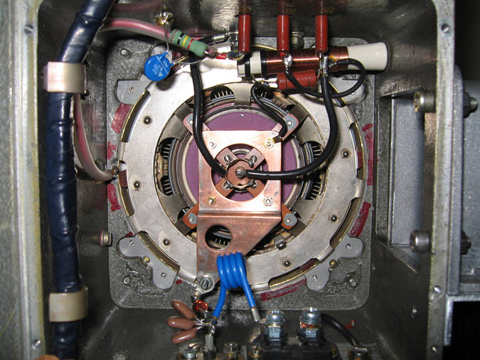
A GU-78b good socket OK to fit in R-140: top view
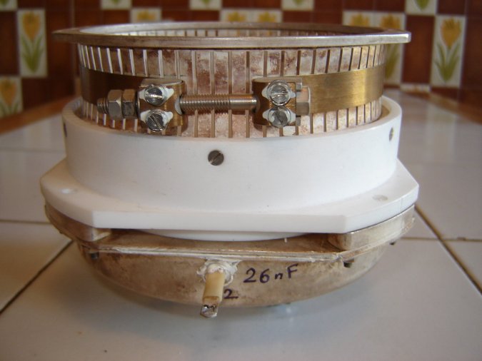
A GU-78b good socket OK to fit in R-140: side view (G2 Decoupling 26 nF)
A GU-78b good socket OK to fit in R-140: bottom view
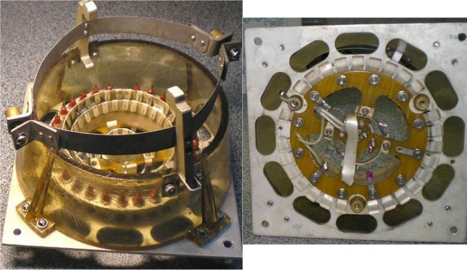
A GU-78b VERY good socket unfortunately too large to fit in R-140
without important modifications like OE3RTC has done. See later-on
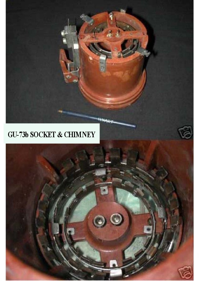
GU-73b tubes, sockets and chimney are more hard to find and install, but fully acceptables.
Datasheets and pictures of tubes and sockets are available here for download:
GU-78b dimensions & sockets , GU78b datasheet1 , GU78b datasheet2
GU-78b Cooling data , GU-73b datasheet1 , GU-73b datasheet2 , GU-73b data
GU-73b Socket , GU-93b datasheet
------------------------------------------------------------
PREPARATION OF THE WORKS
New antenna relay, for R-140 with GU-78b, with 1/4" PTFE Andrew coaxial cable.
Pay attention to installation, to avoid mechanical & thermal stresses on relay.

New enclosure with DIN 7x16 connectors


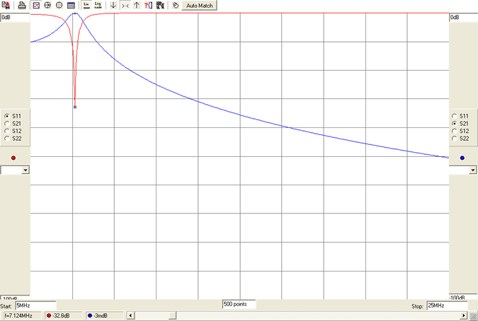
What will follow is the results of measurement campaigns, made "cold" on my amplifier, today equiped with tube Q-1P/42, with MiniVna network analyser connected at amplifier output.
A 1000 ohms resistor and a 30 pF capacitor where placed between tube anode and ground, to see what would happend, and try to predict future working conditions ....
MiniVna measurement example screenshot on 1.8 MHz.

EXCEL file for approximative calculations.

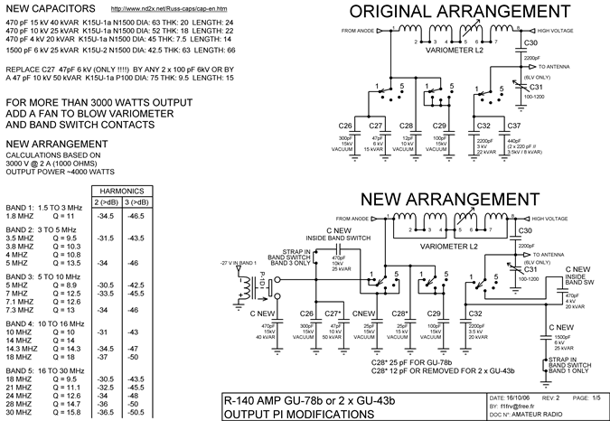
Schematic diagram of the modifications.


SIMULATIONS WITH RFSIM99
RFSIM99 is a simulation freeware available on the net in english and russian.
You can see the good matchings, and 2nd & 3rd harmonics rejection expected
1.8MHz (to be compaired with MiniVna measurement !!! )

3.5 MHz

7 MHz
14 MHz

28 MHz

You can download all this, with PDF, EXCEL & RFSIM files: R-140_GU78_OR_2xGU43.zip
All pertinent comments, and ideas are welcome...
![]() Dominique - f1frv@sfr.fr
Dominique - f1frv@sfr.fr  OR
OR 
Thanks a lot to Walter OE1WWA, Dieter OE3RTC, who, some time ago, already made modifications of these amplifiers, with one GU-78b, and gave me very very precise information about what to do, and also, what to take care of, and, what to avoid ...
Some pictures of OE3RTC works


Link to RFSIM simulation freeware in English: HERE
Link to RFSIM simulation freeware in Russian: HERE

