All powers SWR bridge and power meter 1st edition: may 2004 Revision 17: january 2024 |
by Dominique - F1FRV
Tous droits réservés (Copyright) F1FRV
* Toute utilisation de ces données à des fins commerciales est soumise à mon accord préalable *
* Any commercial use of these data is subject to my prior approval *
* january 2024 Updated explanations in text & excel sheet *
Aide technique (Français) Droits d'auteur (Copyrights)
EXCEL sheet with toroid true measured AL input.
![]() Peak power optional board (link at bottom of this page).
Peak power optional board (link at bottom of this page).
SWR AND POWER MODIFIED BRUENE BRIDGES
This design is applicable for small or high powers, from 100 kHz (or less) to 50 Mhz, from miliwatts to kilowatts, depending on the selected components. For best results, for WIDEBAND use the ferrite "43" material. Materials "4C6 or 4C65" generaly painted in purple, are identical to material "61" and can also be used (with much more turns than "43" for same inductance).
Material "2" iron powder (painted in red), were not in tables, as i strongly do not recommand their use for wideband. They works well for monoband designs, but definelitely not for wideband designs.
In theory, "61" or "4C6/4C65" could be used for 144 MHz, but i did not experimented by myselves...
Good suppliers for toroids are: RF microwave.it , KitsAndParts , and AMIDON ...
RF microwave.it and KitsAndParts can also supply 1N5711 and trimmer capacitors.
With good electrical and mechanical design, using parts described here, and PCB designed for, 1.8 to 30 (50) MHz directivity can be better than 35 dB, and accuracy in power measurements in the range 1 to 2 %. Not so bad, isn't it ...
With different electrical or mechanical design, or misunderstanding of the excel sheet, please, do not complain if you obtain bad results, no or poor directivity, or transform resistor and wires into smoke and flammes (1 case in eastern Europe). Hundreds of people all around the world were happy with this design... If it is not your case, please, re-read carefuly what is written, and review what you made.
Generaly, if it dont works, it is with people more clever, and better technicians than me, who dont want to follow EXACTLY what is written, and do what they feel instead. Or people dont using Windows & OFFICIAL OFFICE software (no free bullchit "free office") to use intelligently excel design file provided. If this is your case, no complaints accepted if it dont works.
EXCEL sheet design example
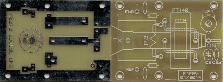
Nota: It is better to select the schematic with one resistor R2 and mid tap at coil, than the other scheme with 2 half values resistors. As it is easier to have EXACTLY the same nb ot turns in coil, than having EXACTLY the same values of the 2 resistors. Any difference in the 2 resistors values would give errors in SWR measurements results. Dont forget that turns number is the TOTAL nb of turns counted INSIDE toroid hole.
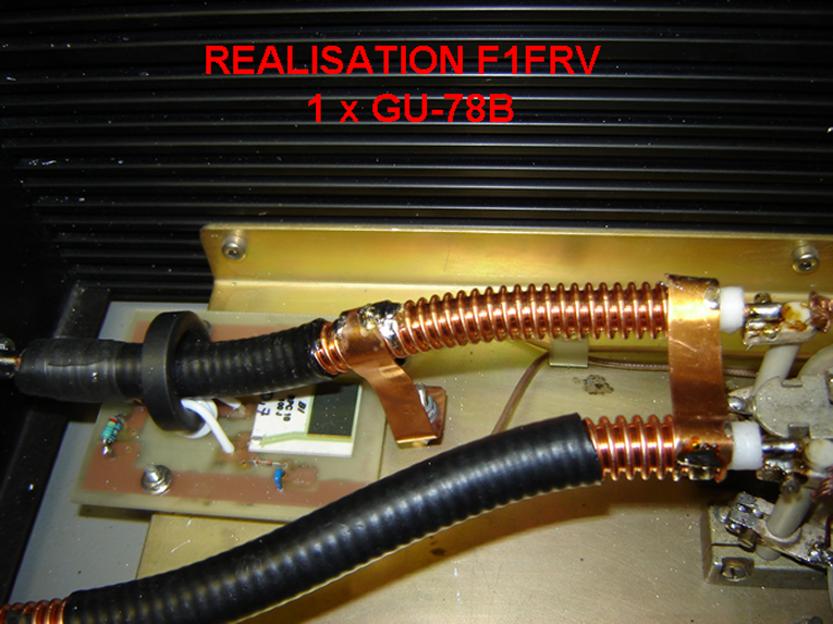
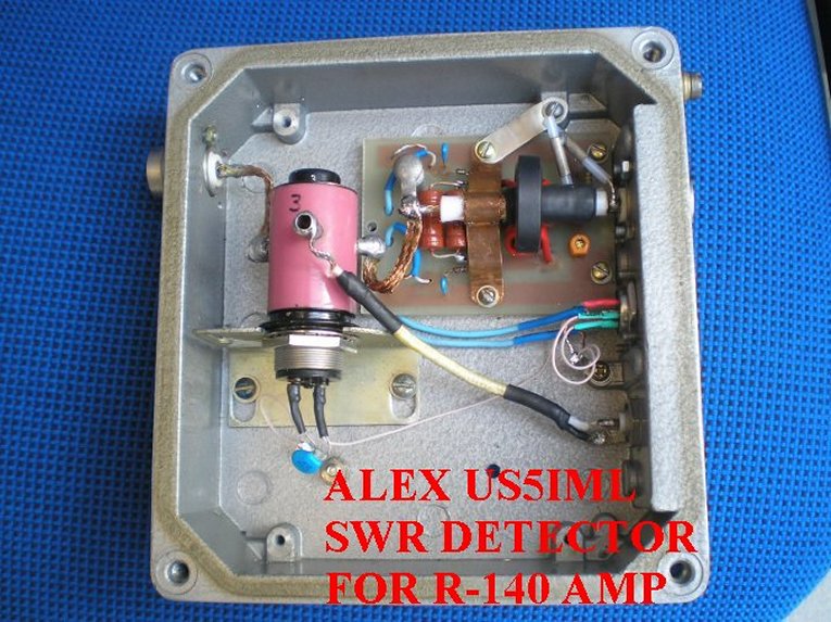
Very IMPORTANT: For wide band service, coaxial line shield must be grounded ONLY 1 side of toroid, 1 time at input connector, and 1 time just near toroid. Place the WIDE (minimum 10 mm) ground return strip(s), not a single wire, between coaxial line shield, circuit board and/or main ground frame, as close as possible to the toroid, to have the best accuracy in POWER measurements over a wide range of frequencies. For SWR measurements ONLY, this is not very important, as the ratio FWD/REF is independant of absolute values of detected voltages.To avoid parasitic capacitances, place the PCB at least 5 to 10 mm above metallic enclosure,
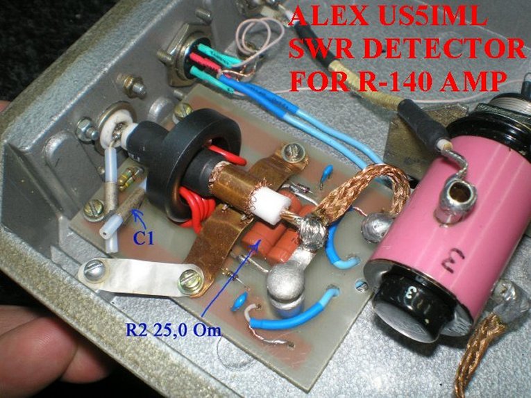
To have perfect balance of the bridge, with the calculated values given by EXCEL sheet, it is important to know the " TRUE " values of the coil(s), resistor R2, and capacitor C1. To know what is the exact Al value of your toroid, coil 4 turns of wire into it, measure with a LC meter, and divide value by 16. With an Ohmmeter, adjust VR1 to the value given by excel sheet.The variable C2 capacitor, as shown, is MANDATORY, to compensate for all tolerances in components values, parasitics. During tests, dont hesitate to modify calculated value of C2 (fixed + adjustable value) to obtain the best balance.Tolerances and parasitic capacitances management are unfortunately not exact sciences. Adjustment of phase compensation C2 must be made, ONLY at bridge maximum frequency of use. If null is not OK with calculated C2, readjust slightly, at max frequency of use, to obtain perfect null. Reverse bridge in /out to check null symetry. VR1 is made to compensate C1 inductance at the lowest frequency to have same values for V FWD & V REF at the lowest frequency and at the highest frequency. If necessary readjust slightly RV1, only at the lowest frequency.
Check of coil(s) and capacitor C1 exact values can be made with a LC meter, like the LC200A or BM4070 you can find easyly in ebay, aliexpress or others at correct price. C1 voltage must be at least what is given in EXCEL calc file wih your max power.
Adapt cross sectional area of wires in toroid to maximum current in R2, do not undersize, 3 Amps by square milimeter is a maximum. Use insulated wires (~50 V mini) preferably to enameled wire, or use additional PTFE tubing. This insulation is to limit parasitic capacitances between turns wich degrades wideband accuracy.
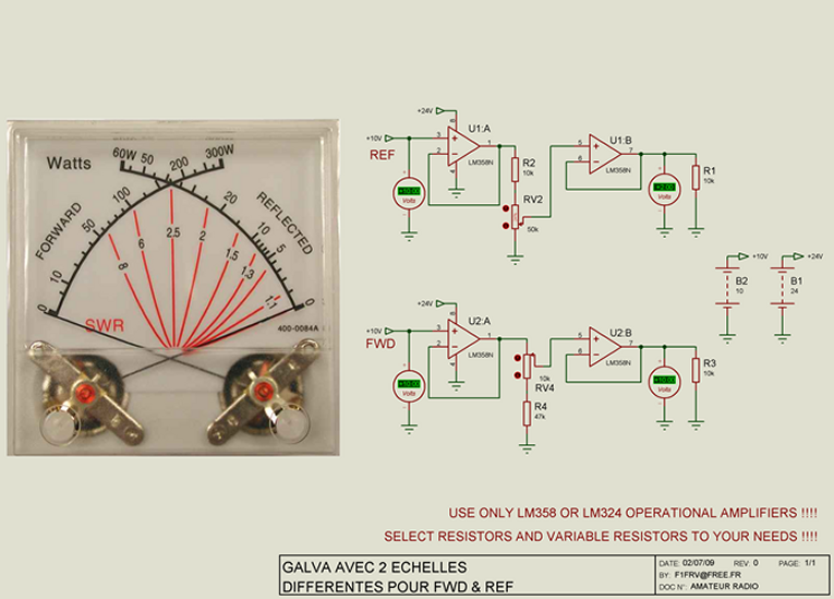
Load on detector diodes is a first order parametre for rectified voltages output. Do not hesitate to use operational amplifiers LM358 or LM324 as buffers (they include GND in common mode range). In this case, with very high impedance detectors load, to avoid too high time constant in SWR readings, reduce, if necessary, the values of decoupling capacitors (ceramic) in FWD & REF outputs. 4.7 to 10 nF is OK with operational amplifiers, 100 nF or more without operational amplifiers.
PCBs & some parts availables. See HERE
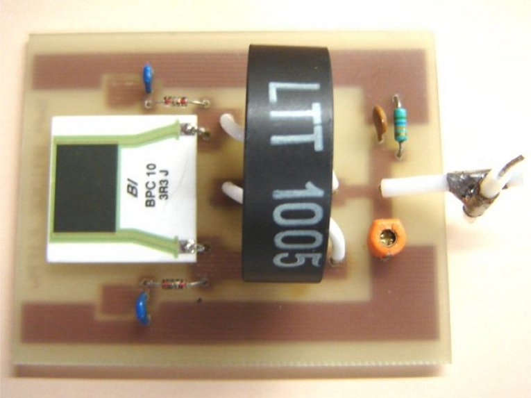
Note the wide ground strap behind toroid
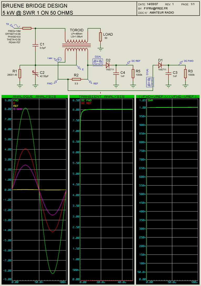
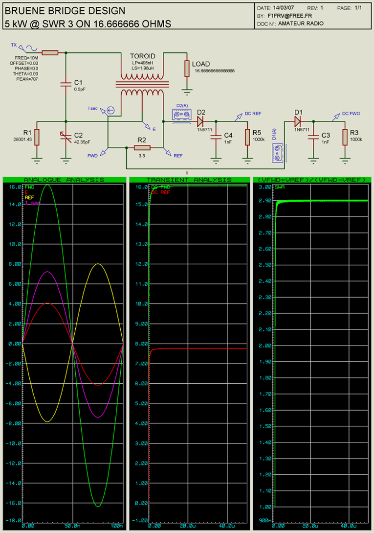
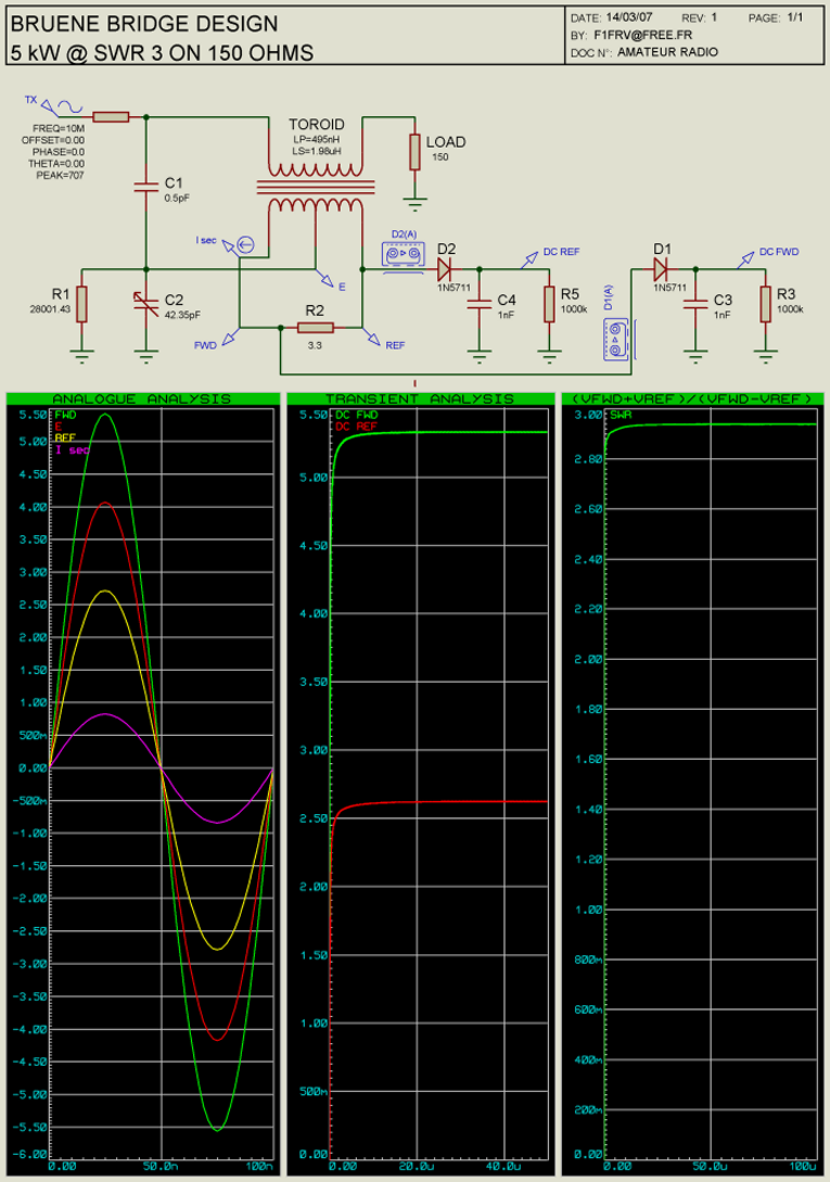
Simulations of the bridge phase & balance
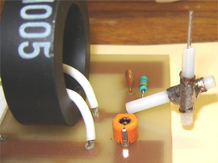
Bridge old revision 3 PCB & components picture
Detail of the 0.5 pF @ 4000 V capacitor ( 2 x 10 mm of copper of RG402 )
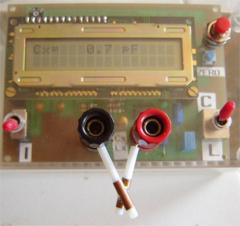
Measurement of a 0.7 pF @ 4000 V capacitor ( 2 x 14 mm of copper of RG402 )
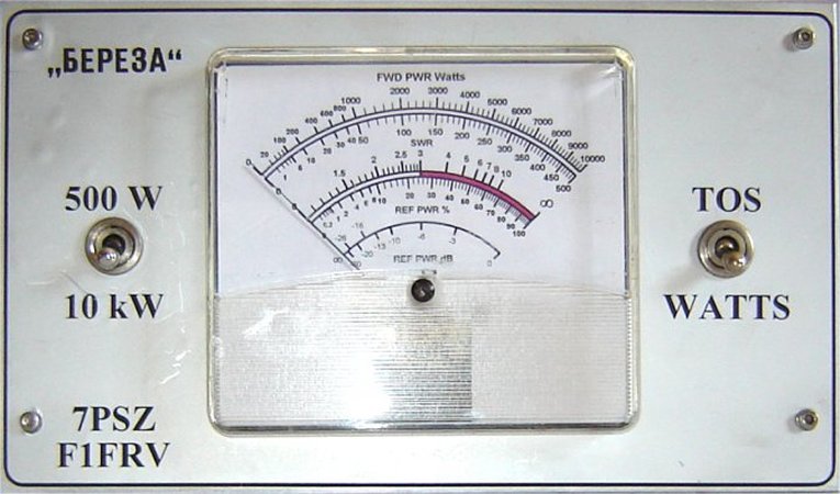
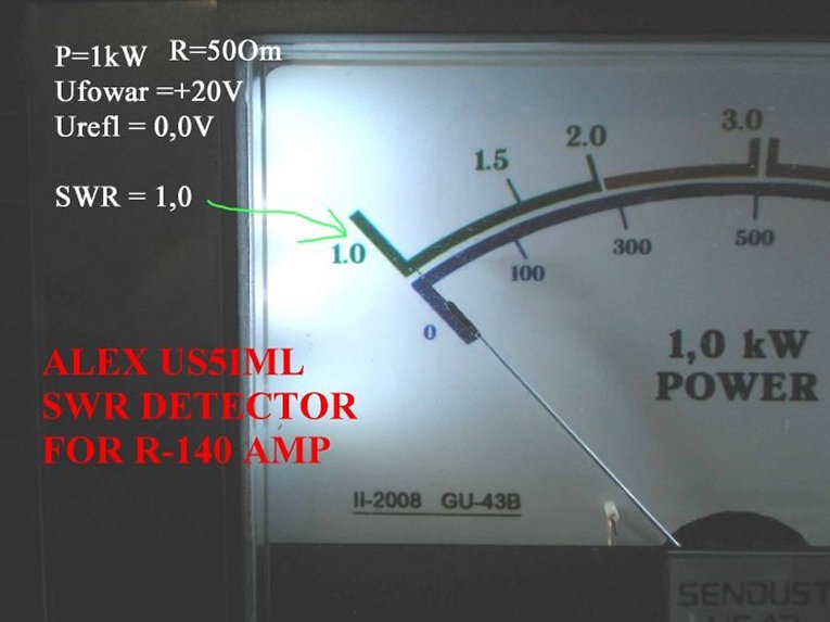
Front plate with meter
Meter scales can be made with F5BU’s POSTCARDWARE “GALVA” available HERE.
Download EXCEL sheet, components datasheets, and files for PCB: SWR bridge F1FRV.ZIP
Internal link to SIMPLE PEAK WATTMETER BOARD
Internal link to Automatic SWR meter
PCBs & some parts availables. See HERE
Enjoy ! !
Dominique - f1frv@sfr.fr
OR