RUSSIAN AMPLIFIER R-140 RF SWITCH, DUMMY LOAD AND ANTENNA SWITCH by F1FRV Rev 1: December 2006 |
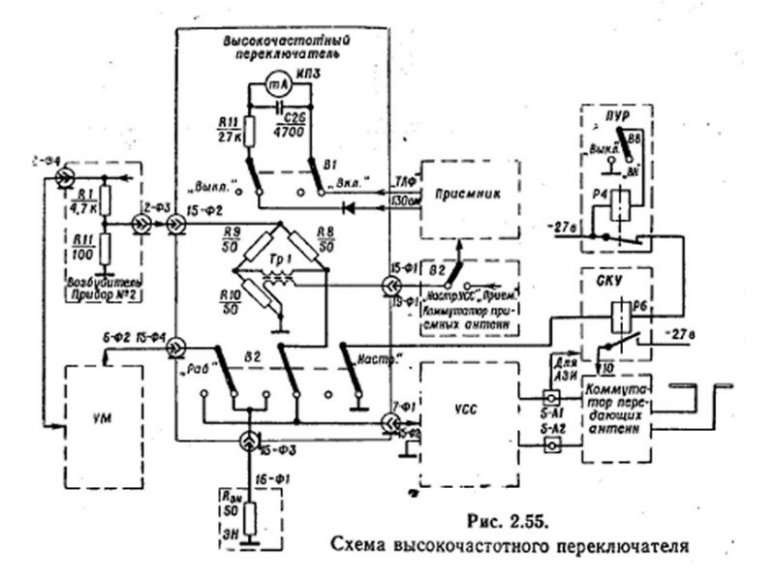
This equipment (UNIT 15) is used to connect the output of the amplifier (YM), to tune it on a 50 Ohms load, before using it on an antenna or entering the antenna tuner (YCC). It is associated with a "dummy load" 50 Ohms (UNIT 16) with non inductive power resistors.
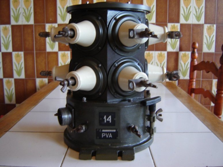
The motorised remote antenna switch (UNIT 14) is placed at antenna tuner output, via a bifilar feeder, to select 1 out of 5 different antennas.
In the RF switch, the front plate meter is not directly associated with the internal LOW POWER impedance bridge. Do not connect neither amplifier output, nor 100 Watts class driver to this bridge. Note also that this RF switch has poor SWR performance, his reactances are compensated by amplifier matching output circuit.
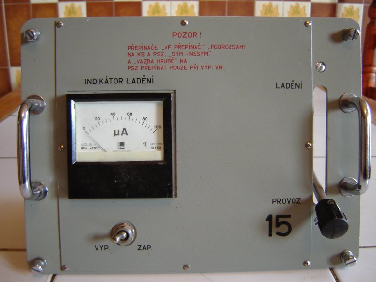
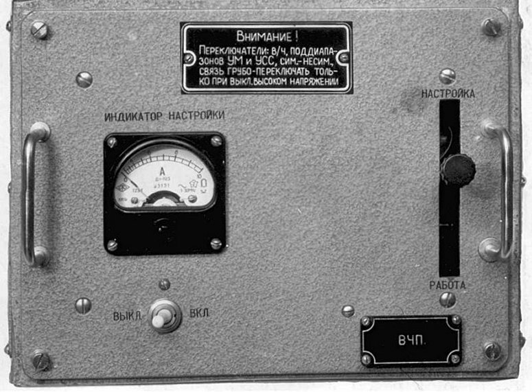
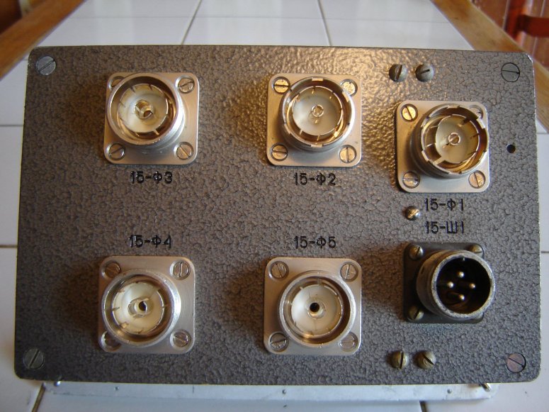
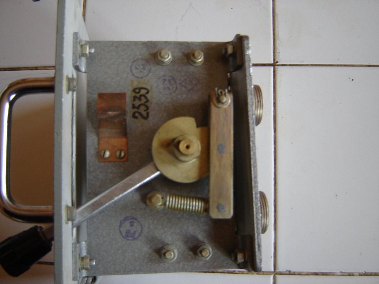
The RF switch UNIT 15
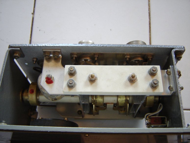
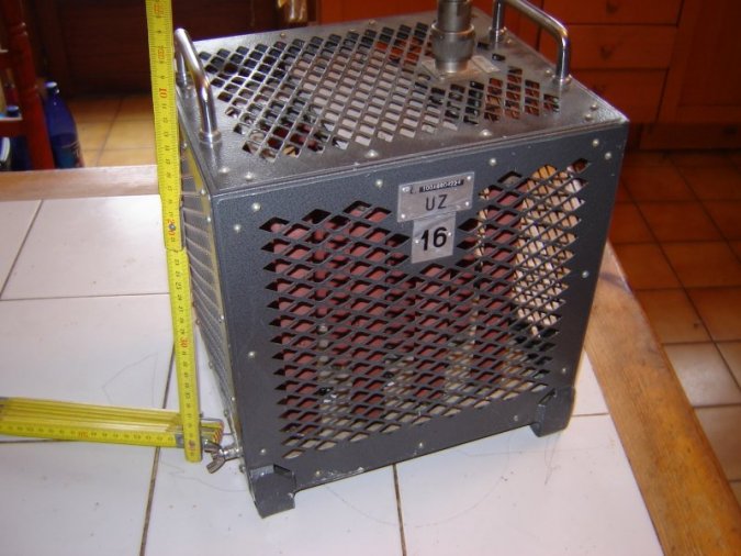
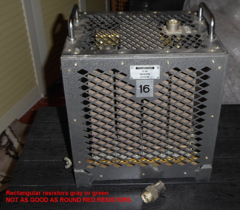
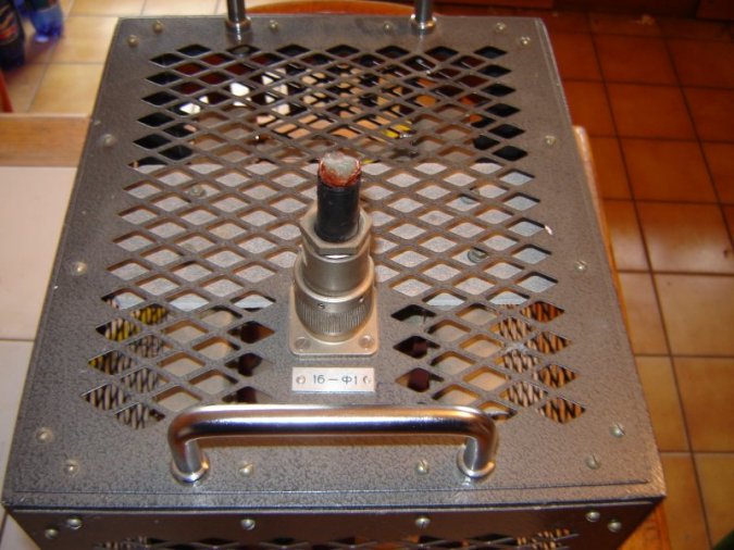
The "dummy load" UNIT 16
Beware, some are with ONLY 12 resistors 600 Ohms,
some (better) are with 20 resistors 1000 Ohms.
SWR & cooling with round resistors are better than with rectangular resistors.
Before purchasing, ask precisions to supplier.

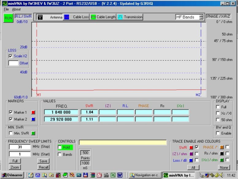
DUMMY LOAD SWR CURVE FROM 1 TO 30 MHz
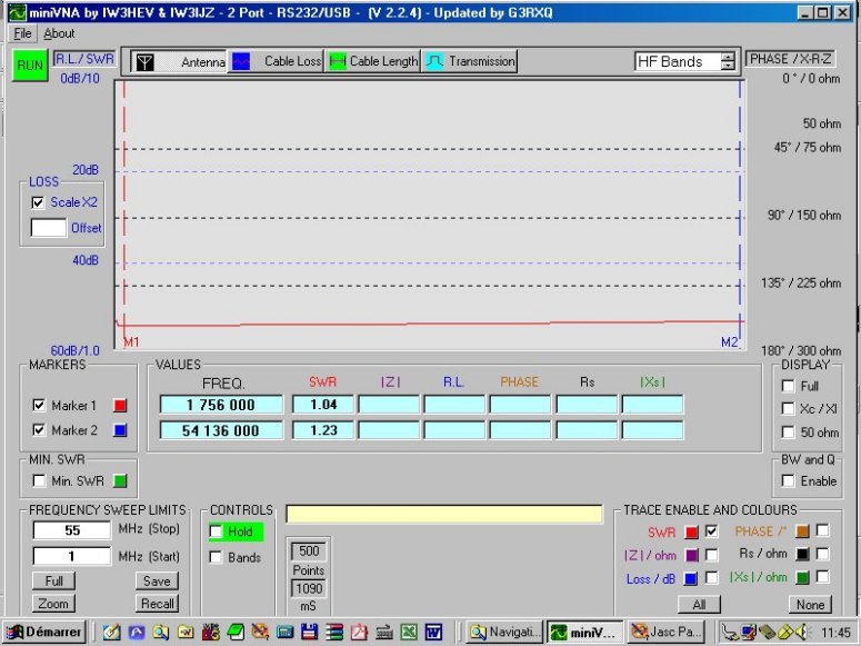
DUMMY LOAD SWR CURVE FROM 1 TO 54 MHz
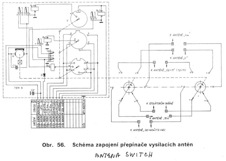
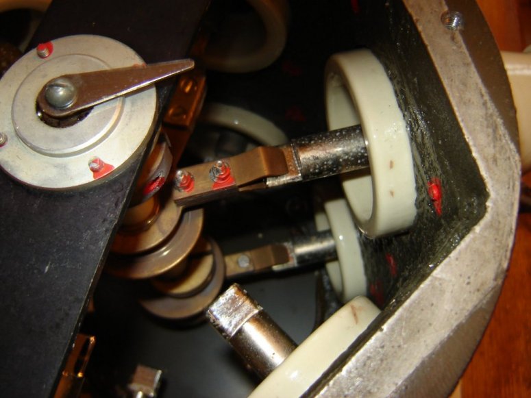
UNIT14: THE 5 ANTENNAS SWITCH
This antenna switch was placed on roof top of R-140 mobile stations.
Download schematic diagram of UNITS 14 & 15 here: Units 14 & 15 Sch.zip
Internal link to "7PSZ" R-140 antenna tuner
|
(English translation) |
Links to other R-140 documentation |
(English translation) |
Special thanks to some hams, who helped us to find technical documentations,
Pavel Vachal OK1DX, Milan Rusky OK1MR, Ludek Odehnal OK2ZC, and www.cqham.ru.
![]() Dominique - f1frv@sfr.fr
Dominique - f1frv@sfr.fr  OR
OR