RUSSIAN ANTENNA TUNER 7PSZ FOR RADIO STATION R-140 by F1FRV Rev 2d: June 8, 2006 * Updated September 2007 * |
* For the fun, click on the rotating red "tools" *
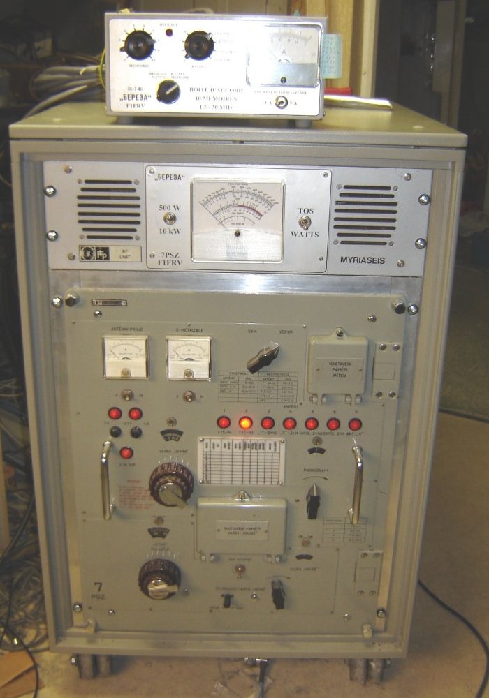
This cold war era equipment![]() is a semi automatic (10 memories) 1,5 to 30 MHz antenna tuner.
R-140 stations have been used in all Warsaw pact countries, with front panel in each local language. Original service was for 1 kW, but, all components can whistand without heating 5 kW... There are two ways of using this equipment: Alone with any transceiver, or with the R-140 amplifier.
is a semi automatic (10 memories) 1,5 to 30 MHz antenna tuner.
R-140 stations have been used in all Warsaw pact countries, with front panel in each local language. Original service was for 1 kW, but, all components can whistand without heating 5 kW... There are two ways of using this equipment: Alone with any transceiver, or with the R-140 amplifier.
In any case, 10 preset tunings, and 5 antennas (asymetric or symetric) can be memorized. Input is asymetric (coaxial cable) and output can be either asymetric or symetric.A local or remote control box is easy to build, to manage the "engine". Just a 27 V DC @ 5 to 6 Amps supply, and few switches are necessary. Adaptation to original RF input special connector has to be realised.
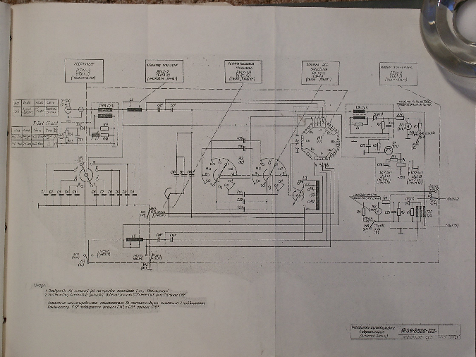
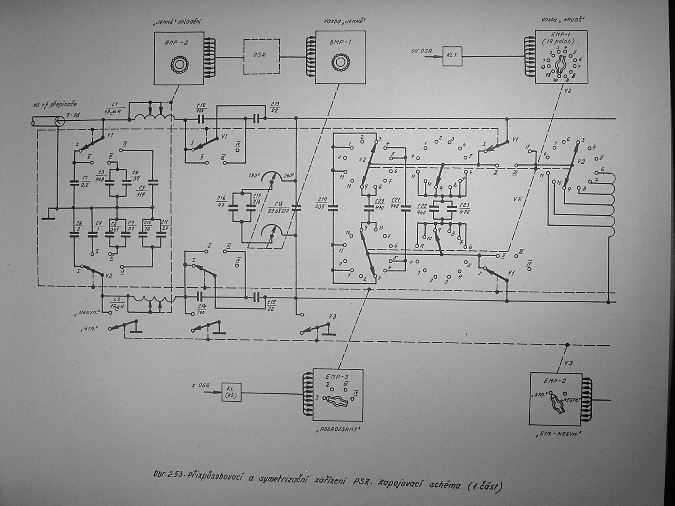
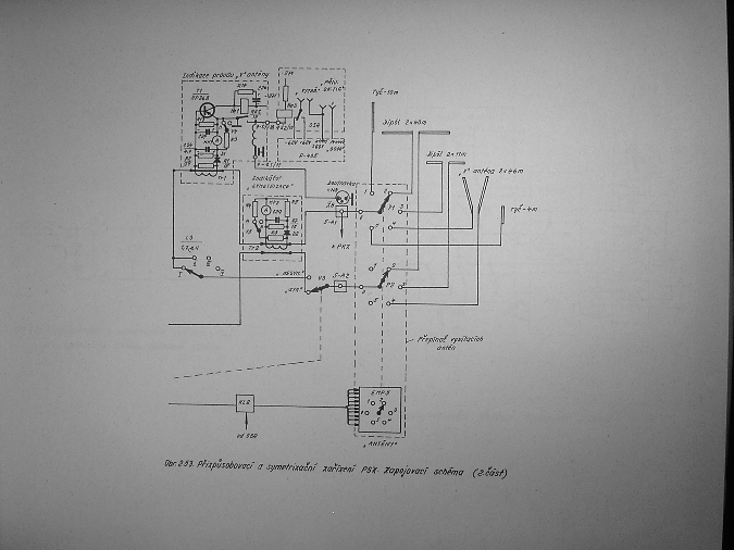
Tuner simplified schematic diagrams
. 
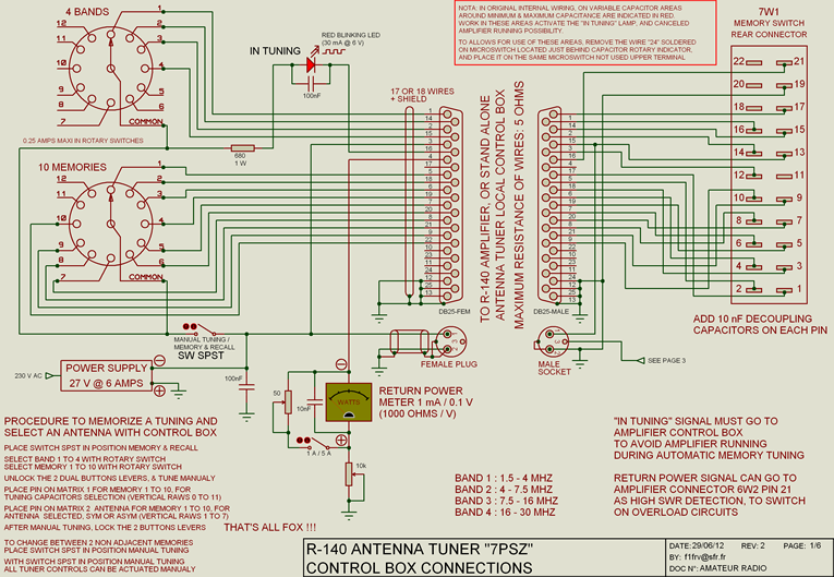
Schematic diagram of the control box
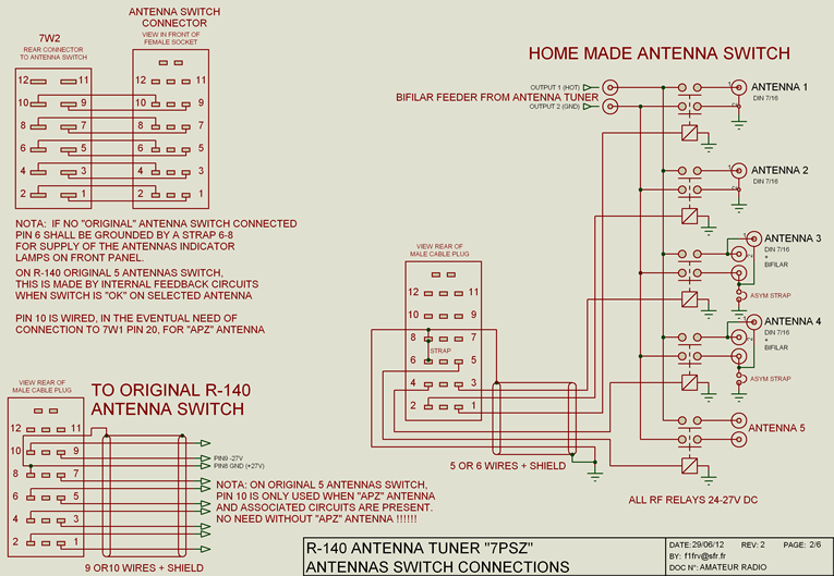
Schematic diagram for optional antenna switch
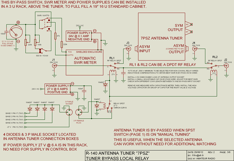
Schematic diagram of optional by-pass
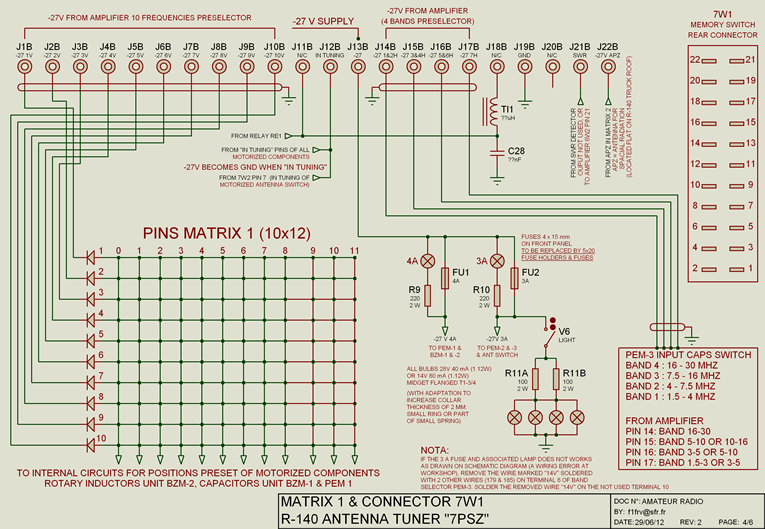
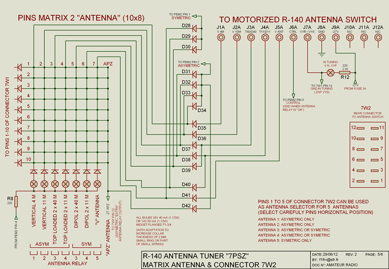
Connections and pins matrix schematic diagram
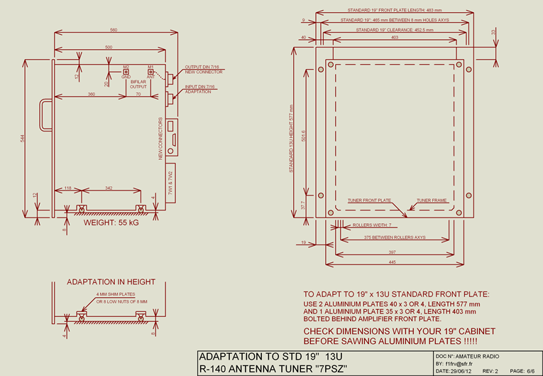
Main dimensions and 19" rack adaptation
Some pictures (click to enlarge)
 |
 |
 |
Tuner (~55 kg) Front panel and right side
 |
 |
 |
Right side details and left side details
 |
 |
 |
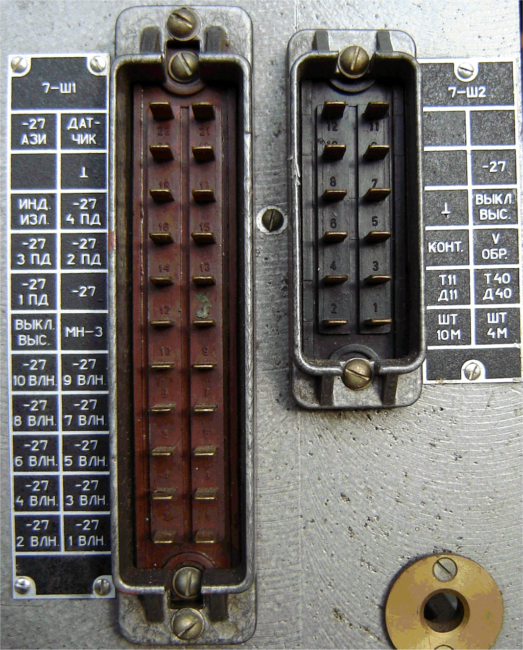
Rear connectors 7W1 & 2, antenna outlet connectors & matrix 1
 |
 |
 |
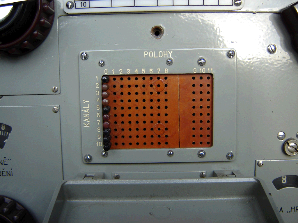
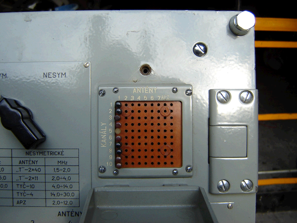
Matrix 2 (antennas), antenna switch, and tuning positions hand writing board
 |
 |
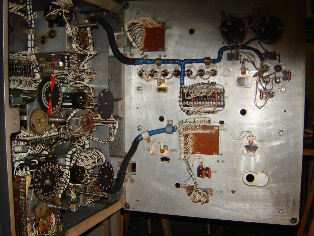 |
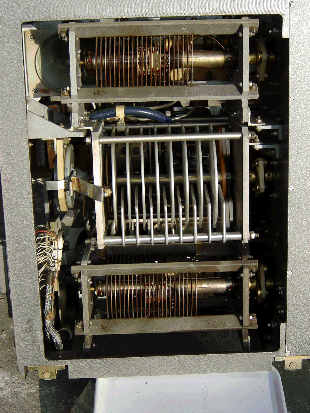
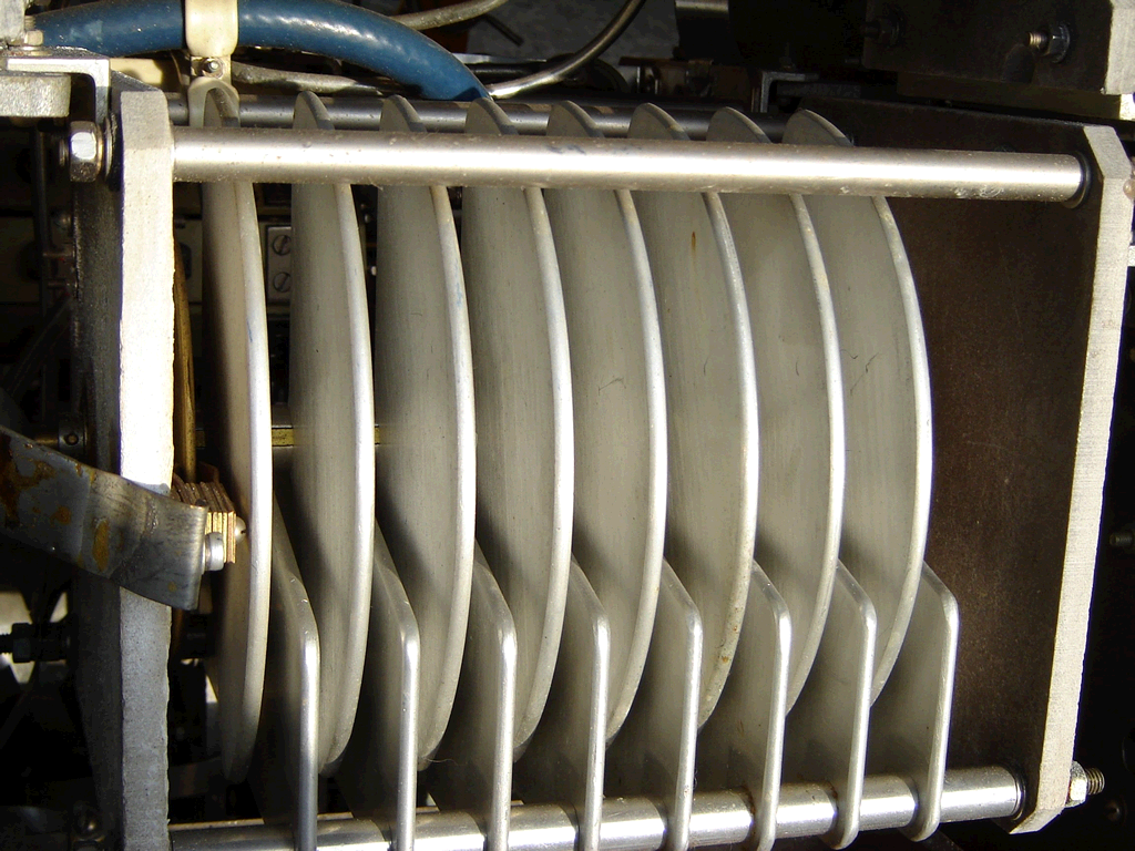
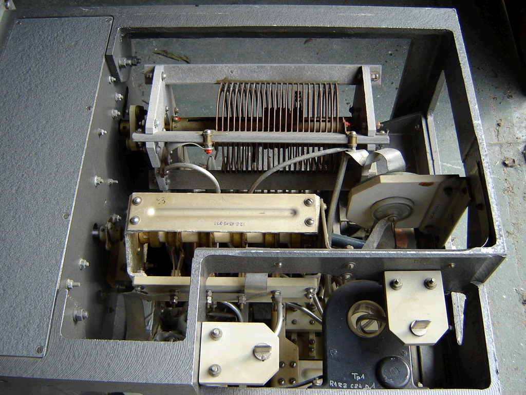
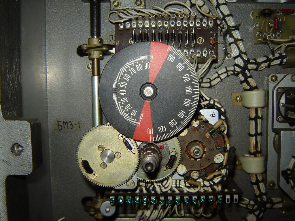
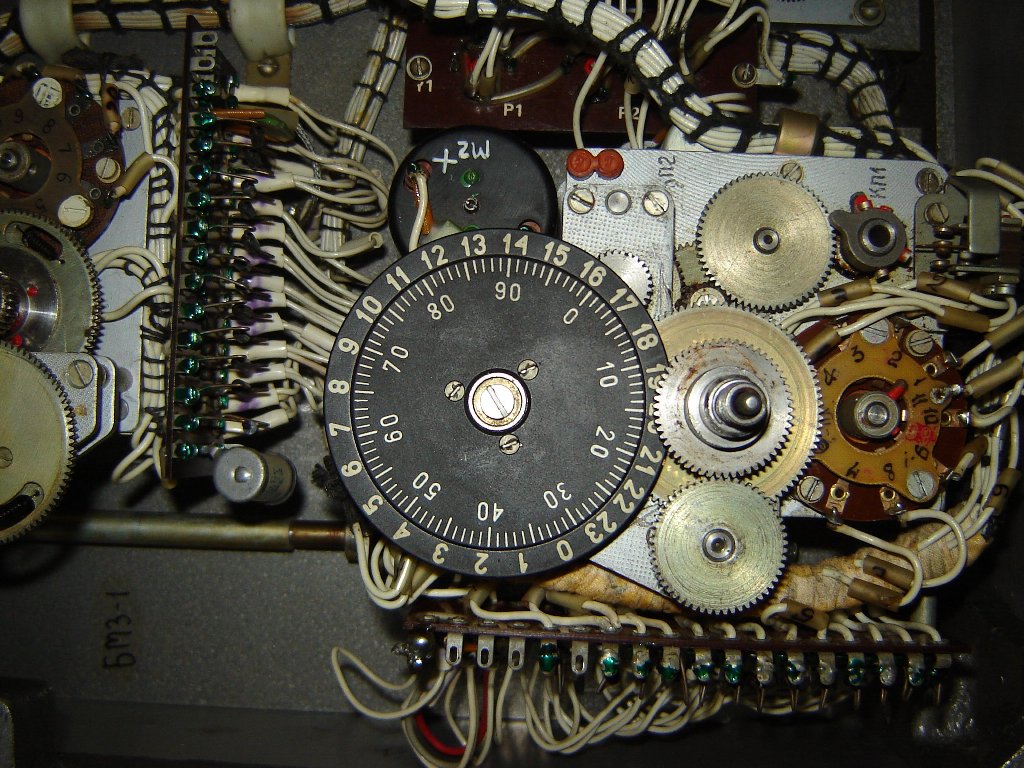
Internal details, nice mechanical job, done from the 60's up to ~1985...
******************************************
Unit 14: The 5 antennas remote switch (~15 kg)
 |
 |
 |
Home made works
Click on pictures to enlarge
 |
 |
 |
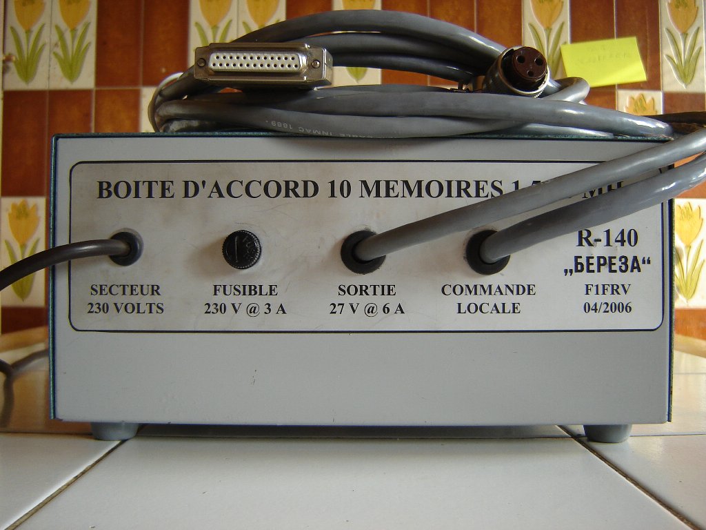
Control box, for use of tuner without R-140 amplifier
 |
 |
 |
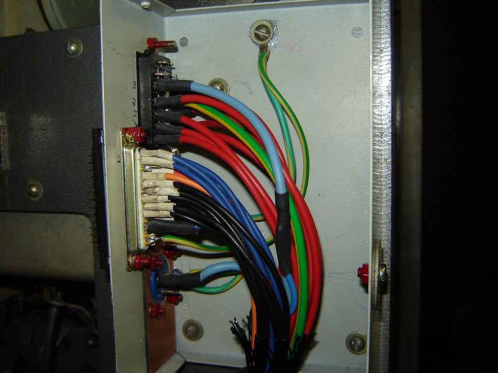
Rear panel (DIN 7X16 input adaptation) and decoupling capacitors
 |
 |
 |
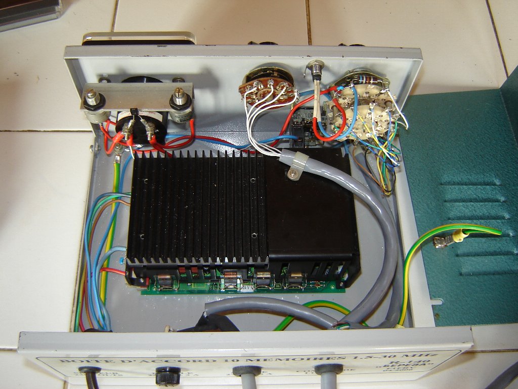
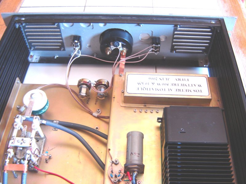
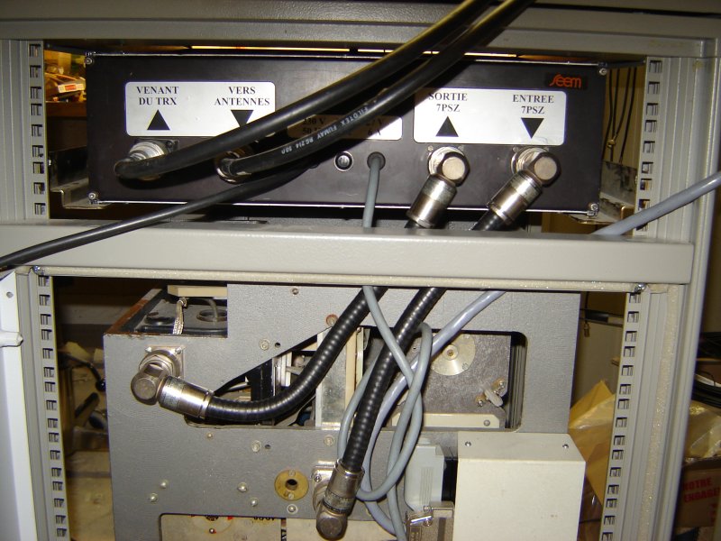
3 U Rack including tuner by-pass relay, and automatic SWR / Wattmeter
 |
|
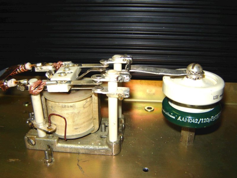 |
By-pass relay and SWR compensation capacitors
 |
 |
 |
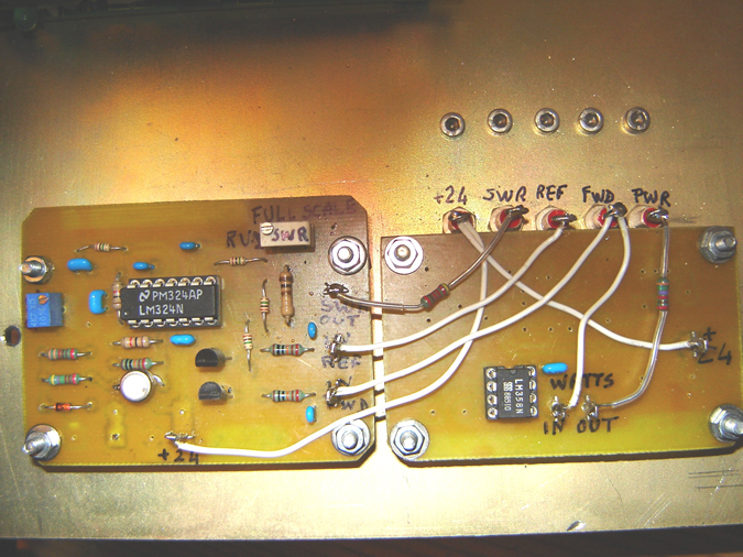
SWR detection, automatic SWR & power boards, necessary shielding
 |
 |
 |
New sym antenna location and new DIN 7x16 asym antenna outlet
Front and rear views of my antenna tuner and by-pass rack
Links to other R-140 pages |
Internal link to the 5 antennas remote switch and fictive antenna
Special thanks to some hams, who helped us to find technical documentations:
Stefan DL1ROY, Zdeno OK2ZW, Ludek OK2ZC, Milan OK1MR, Pavel OK1DX
Download schematic diagrams (rebuild & detailed originals): 7PSZ_doc.zip
![]() Dominique - f1frv@sfr.fr
Dominique - f1frv@sfr.fr  OR
OR