Linear amplifiers cold adjustments with network analyser (VNA) by F1FRV |
* Rev 0 Juin 2009 *
* August 2012: added input circuits *
![]() * April 2015: added HV supply cold RF point adjustment *
* April 2015: added HV supply cold RF point adjustment *
Part 1 Output circuit
Borrow or buy a network analyzer like the DG8QAQ VNWA, MINIVNA, or Agilent / HP.
1. Connect the VNA port 1 to the output of the amp. Amp is off and unplugged !!
2. Leave the tube or tubes connected, and install a resistor from the plate connection to the frame ground.This simulates the output resistance of the tube or tubes. 1/4 or 1/2 watt resistor is OK (preferably carbon, so it is non-inductive, but not mandatory up-to VHF).
To calculate the resistor value, you can use the EXCEL sheets:
For HF amps, see main3d_pi.html , download and use “CALCUL_PI_ F1FRV_Fr_&_Us_”.
For VHF / UHF amps, see main1L_Tetrode_Amp_Design.html, and use “Calcul Ligne SORTIE Cavite Ampli”.
The complete explanation is in the downloads, at bottom of this page.
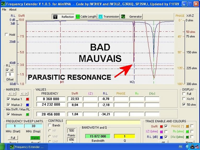


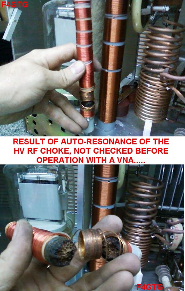
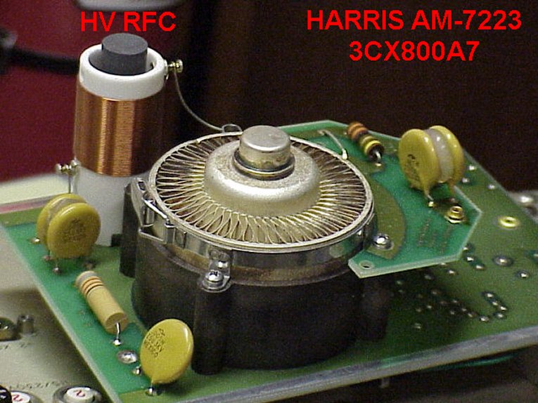
A typical BAD HV RF choke

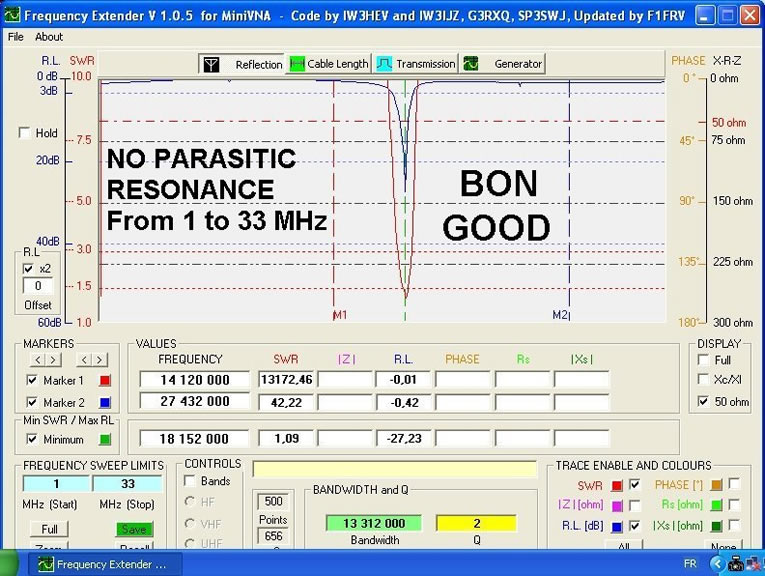
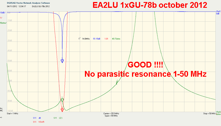
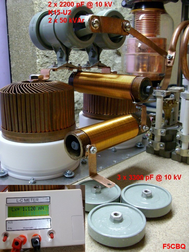
Typical GOOD HV RF chokes with ferrite core

![]() HV supply cold point setting
HV supply cold point setting
This procedure is applicable to VHF or UHF cavity. Position of HV supply in RF output line is important to not send RF to HV supply.
1. Connect VNA port 1 to the ouput, like described in part 1 (top of page). Cold tune for output best match.
2. Connect VNA port 2 to HV power supply cavity connector. Inside amp, disconnect HV decoupling capacitor and replace (or strap) HV choke coil by a wire.
3. Move HV applying point along anode resonator to obtain minimum signal in VNA port 2.
4. Re install HV RF choke & decoupling capacitor. Re check with VNA, there should be no measurable level in port 2.

Part 2 Input circuit
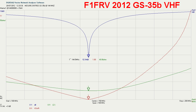
1. Connect VNA port 1 to the input of the amp. Amp is off and unplugged !!
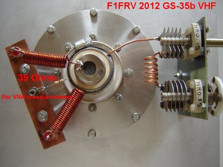
2. Leave the tube or tubes connected, and install a resistor from the cathode (for GG amps) connection to the frame ground. This simulates the input resistance of the tube or tubes. 1/4 or 1/2 watt resistor is OK (preferably carbon, so it is non-inductive, but not mandatory up-to VHF).
To calculate the resistor value, you can use the EXCEL sheets:
For Grounded Grid amps, download and use “Calcul_ENTREE_Ampli_Grille_a_la_masse.zip”.
For Tetrode amps, see main1l_Tetrode_Amp_Design.html, download and use “Calcul Entree Tetrode”.
Triode VHF input example
Download all explanations in the complete file: Linear Amplifier Cold Adjustments.zip
That's All Fox !!!!!
Enjoy !!!!
![]() Dominique - f1frv@sfr.fr
Dominique - f1frv@sfr.fr  OR
OR