|
2 x
GS35b (OR OTHER TUBES) IN GROUNDED GRID LINEAR AMPLIFIER DESIGN |
Tous droits réservés (Copyright) F1FRV
Part 1: Logic card (OLD REVISIONS)
For last revision, see HERE
The logic board can be used, either for tetrode, or for triode amplifiers.
Revision 2: november 2010, Update 2f: march 2011
Revision 3, december 2013. Professional PCBs now available, see HERE
Revision 3a, may 2014, some small components modifications.
This is only for those who dont want to built a wiring mess, without schematics, and without enough safety for them and equipment, but accept to pay what is minimum necessary (only a few among hams). No technical changes between rev 2f and rev 3 (except 2 side PCB, with solder resist and silkscreen).
This NEW and less sophisticated card, replace the old 2005/2007 board since november 2010. Associated with the cathode control and meters card it performs the main functions required by a power triode grounded grid amplifier (except amplification). Replacement of now expansive "S2" relays by low cost and easy to find relays. A front panel circuit board, with leds and switches is now available.
The main features are:
- Switched and fused mains outlets for heaters, auxiliary and antenna relays power supplies.
- Tubes heaters “soft start” to limit inrush current and extend tubes life.
- Start-up timer to allows for tubes heating ~ 3minutes before being ready to operate.
- Blower delayed stop, after amplifier switch off ~ 3 minutes. Blower protection fuses for operator safety, as blower is not switched by amplifier on-off switch.
- All board inlets and outlets by screwed terminal blocks.
- Cathode control via opto-isolator and Mosfet or Darlington transistor.
- Cathode adjustable voltage regulation circuit, with protective devices.
- Grid and plate current meters shunts and dividers.
- PTT logic timers to avoid “hot switching” and perform controlled sequences during transmit-receive operations. This circuit allows also for RX preamplifier control.
- Single side printed circuit boards (with a few straps) have been chosen for easier ham home made realisation. Now, professional dual side PCBs are available see HERE.
Not so bad and versatile …. isn’t it ?????????
- Change the values of timings in accordance with your transceiver and antenna relays, if needed.
- Change heater “soft start” resistor value according to tube data.
All values are given as practical example.
As you can see, this design can be easily adapted to other tubes than GS-35b’s.
All components are available at Radiospares or Farnell. Bill of material with prices and Farnell references is supplied.
For information: to build a triode amplifier, total cost for necessary PCBs and related components is less than 200 Euros.
Schematic diagrams


Delayed blower stop alternative timer assembly (thermal switch & heater).

Delayed blower stop, electronic timer Download


PTT logic sequencer & start up timers

Adapt timing resistors and capacitors to your needs. An EXCEL calculation sheet is in the downloads, to help you. Calculated timings are not extremely accurate, as FETs gates voltages for conduction are depending of a lot of parametres, and capacitors leakage current is not taken into account. Do not use resistors higher than ~ 2 Megohms, to limit influence of FET gate and capacitor impedances.
Heater soft start: Calculate " Rx " resistor according to Ohm's law (if you heard about it...), for nominal current of heater under short circuit. As example, for heater 12.6 V @ ~ 6.5 Amps (2 x GS-35b), resistor shall be ~ 2 Ohms (2 x 3.9 Ohms in // ). This limits inrush heater current to ~ 6.5 Amps, (instead of more than 50 Amps), and gives ~ half nominal heater voltage and current to the tube after 5 to 8 seconds. Power of " Rx", for less than 10 seconds of service, can be reducced to ~ 1/2 of calculated average dissipation. In this case, 25 W is OK.
For heater current higher than 10 amps, RL1 shall drive an external power relay.
For tubes like TH293 which needs extended time (>1 minute) at half heater voltage, timing capacitor C2 must be modified for longer time delay. In this case, " Rx" shall accept full heater half power without burning ..

PCB layout


Front panel


Wiring

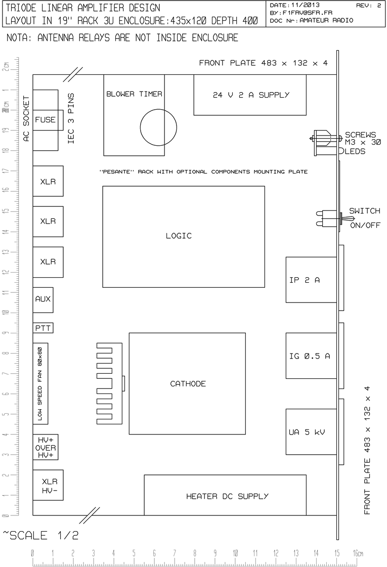
Layout in 19" 3U rack
Some pictures of the cards
Pictures of the cards in a 1 x GS35b amp at 144 MHz
Pictures of the cards in a 2 x GS35b amp at 144 MHz
Links
Internal link to OLD cathode & meters board
Internal link to high power antenna relays
Internal link to slow rise regulated heater power supply
Downloads
Files for 19" RACK,METERS & SUPPLIES (with datasheets & bill of materials)
Files for TRIODE OR TETRODE OLD LOGIC BOARD (with datasheets & bill of materials)
Files for TRIODE OLD FRONT PANEL (with datasheets & bill of materials)
Files for DELAYED OLD BLOWER STOP TIMER (with datasheets & bill of materials)
That’s All Folks ! ! ! !
Dominique - f1frv@sfr.fr
OR