GS35B OR OTHER TRIODES LINEAR AMPLIFIER DESIGN |
Tous droits réservés (Copyright) F1FRV
Part 2: Cathode control & meters
OLD Revisions. New revision HERE
Revision 0 in 2005
Revision 3: november 2010
Revision 3b2: february 2011 (PCB minor change)
Revision 4, december 2013.
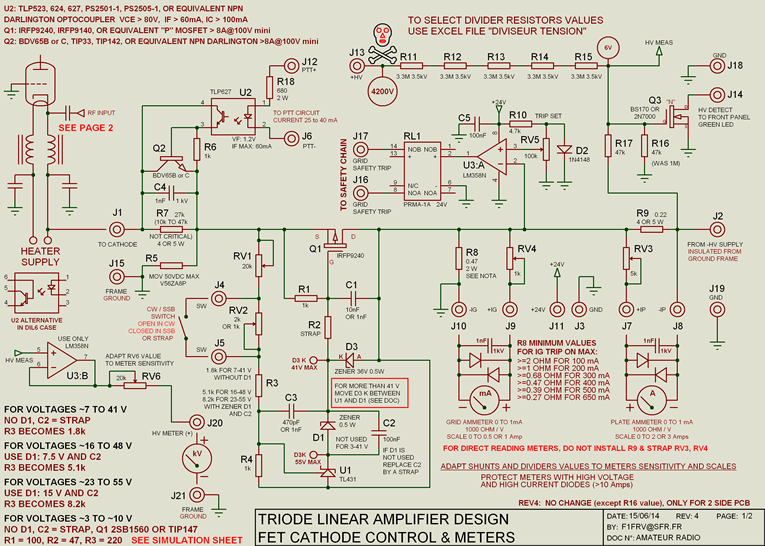
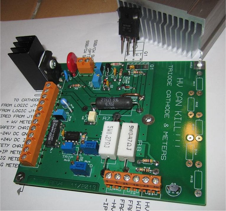
No technical changes between rev 3b2 and rev 4 (except 2 side PCB, with solder resist and silkscreen).This "improved" design, use a power MOSFET instead of bipolar darlington transistor TIP147 or equivalent. The reason is to reduce a bit the huge dissipated power in the bipolar, which result is Q1 breakdown, in a lot of cases all around the world. Even at high cathode current (up-to 3 Amps) no need for "mamouth" heatsink plus blower for Q1 MOSFET.
On high voltage detection, a transistor MOSFET, is added to be compatible with the new logic board. A trip system is implemented, in case of excessive grid current. This relay contact is to be inserted in logic card safety chain. An optional HV meter is added on the board.
This card, associated with the logic card, performs the main functions required by a power triode grounded grid amplifier (except amplification).
This design can be used with any other power triode, not only with GS-35b’s.
All necessary meters are included: grid and plate currents, high voltage. Adapt shunts, resistors and voltages to your needs. All values are given as practical examples. All critical components are available at RADIOSPARES or FARNELL.
Schematic diagram

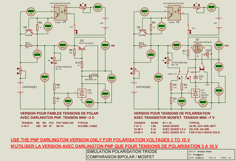
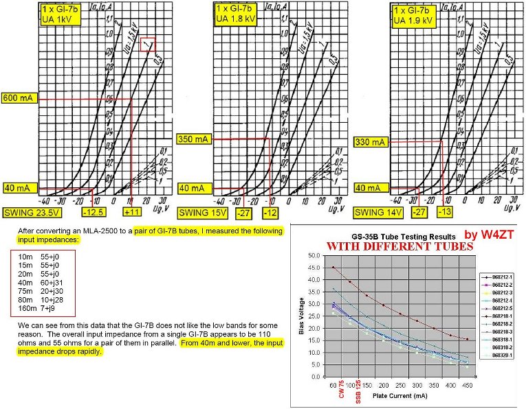
Voltages ranges simulation
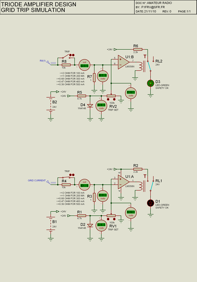
Trip system simulation
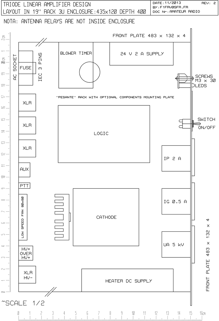
PCB layout
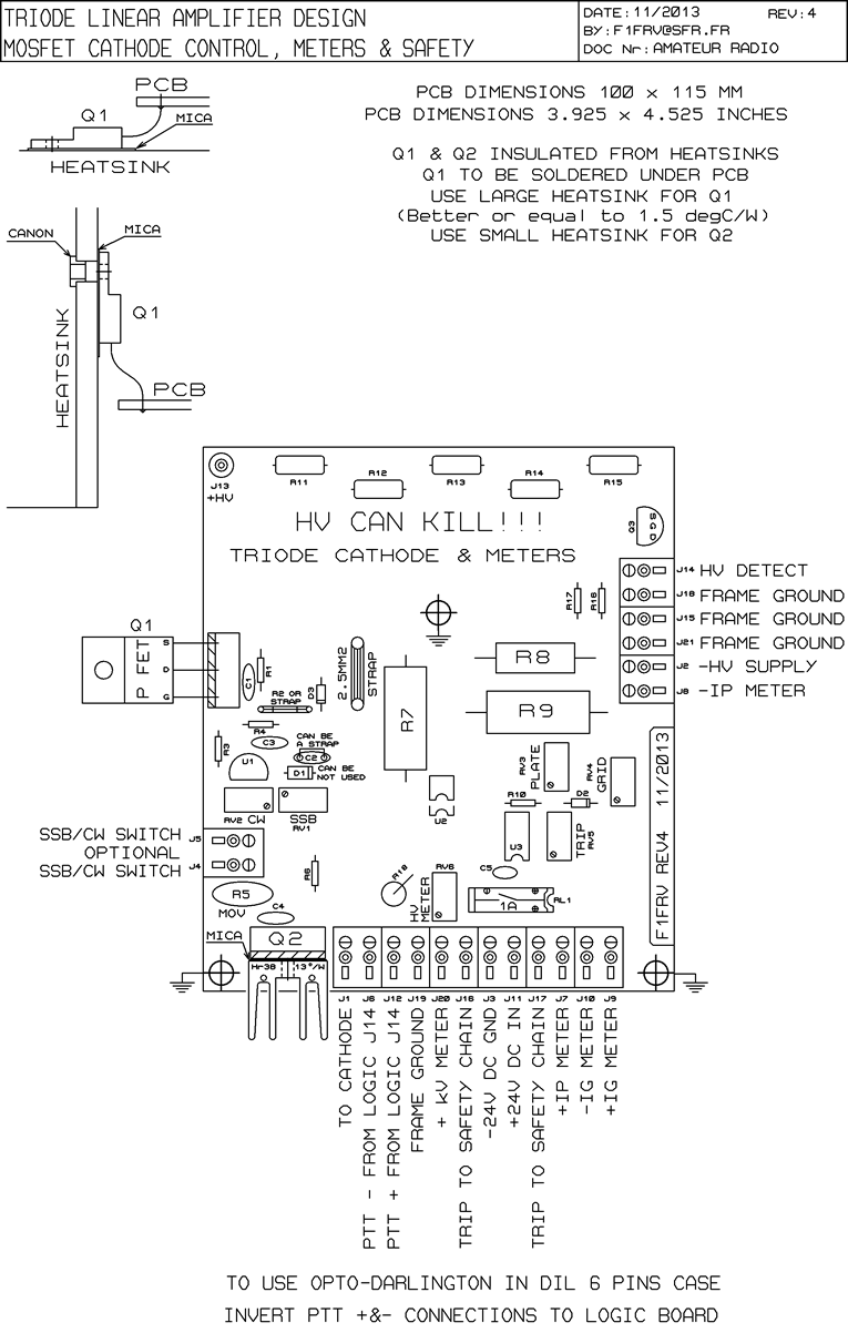
Circuit board
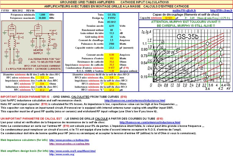
Cathode RF input circuit design
Some pictures of the cards
Pictures of the cards in a 1 x GS35b amp at 144 MHz
Pictures of the cards in a 2 x GS35b amp at 144 MHz
Links
Internal link to OLD logic board
Internal link to slow rise regulated heater power supply
Downloads
Simulation of comparisons between bipolar and mosfet
Cathode input circuit design (excel sheet) Calcul_ENTREE_Ampli_Grille_a_la_masse
CATH&METERS_FET.ZIP OLD REVISION with bill of materials, datasheets, and EXCEL calculation sheets.
That’s All Folks !!!!!!
![]() Dominique - f1frv@sfr.fr
Dominique - f1frv@sfr.fr  OR
OR