RUSSIAN AMPLIFIER R-140 by F1FRV |
Rev6 March 2007, mods: Schematic of adaptation for SDR-1000
Rev7 March 2010, mods: Updated control box layout on PCB and values schematic page 4
Rev7b april 2014, mods: Updated amp & control box schematics.
For the fun, click on rotating "red tools"
This cold war era equipment![]() is a semi automatic (10 memories) 1,5 to 30 MHz linear amplifier. R-140 stations have been used in all Warsaw pact countries, with front panel in each local language. Original design uses a driver stage with 2 x 6E5P small tetrodes for about 100-200 mW input only. Final stage use a 1 kW dissipation glass/metal tetrode GU-43b or Q-1P/41, or a ceramic/metal Q-1P/42.
is a semi automatic (10 memories) 1,5 to 30 MHz linear amplifier. R-140 stations have been used in all Warsaw pact countries, with front panel in each local language. Original design uses a driver stage with 2 x 6E5P small tetrodes for about 100-200 mW input only. Final stage use a 1 kW dissipation glass/metal tetrode GU-43b or Q-1P/41, or a ceramic/metal Q-1P/42.
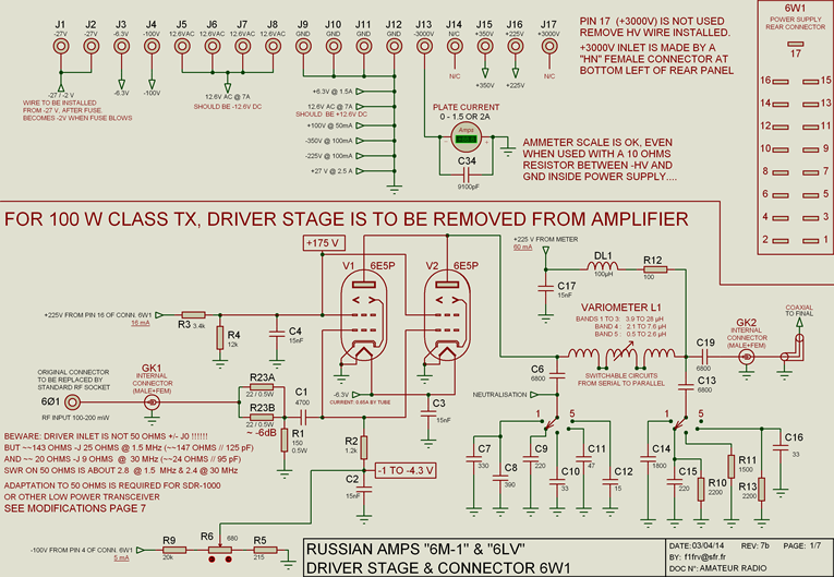
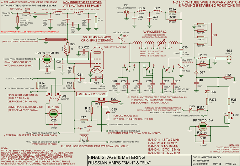
To use it in amateur radio station, with a 100 Watts class transceiver, we removed the driver stage, and made a wide band 50 to 200 W input adaptation, It was also necessary to add blower, antenna relays, covers, logic & safety circuits, and power supplies. With good power supplies, and PI network modifications, in amateur radio service, 1.6 kW RF SSB output can be safely reached. With a GU-78b, power up to 5 kW can be obtained. It is also possible to replace the tube by a GS-35b triode, to simplify power supplies and safeties, and have more output power.
Some improvements on output PI network to have a better match in ham bands can be done, see later-on.
Nota: SDR-1000 low power users will maintain the driver working.
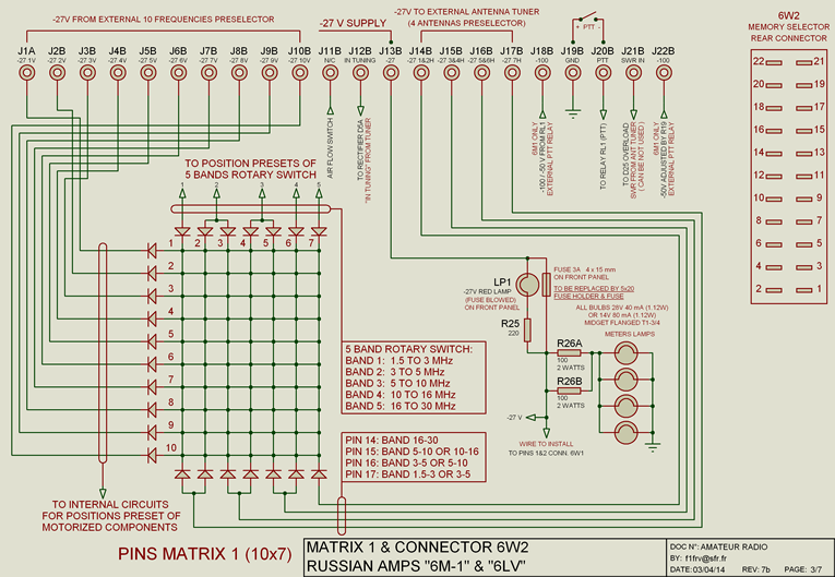
This is the "rebuilt" schematic diagram (updated)
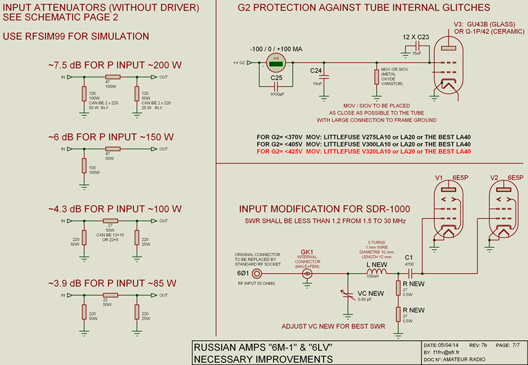
Tetrode wideband input documentation
SIMULATIONS OF DIVERSE INPUT ATTENUATORS
Download non inductive resistors data
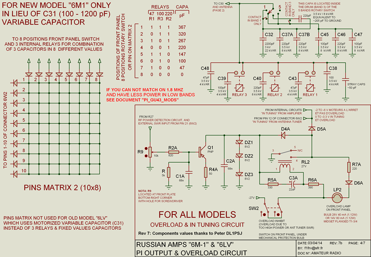
6M1 PI OUTPUT RELAYS & CAPS
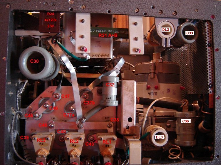
6M1 FRONT PANEL OPEN (very nice mechanical & cabling works)
6M1 OUTPUT PI NETWORK MEASUREMENTS
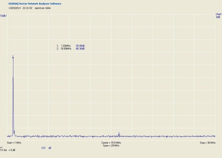
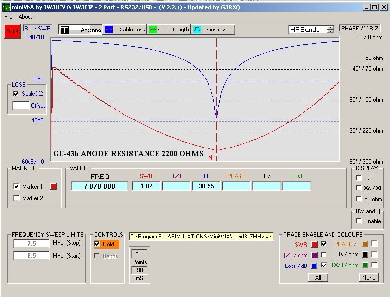
Download all output measurements: 6M1 measurements.zip
***************************************************************
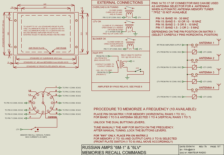
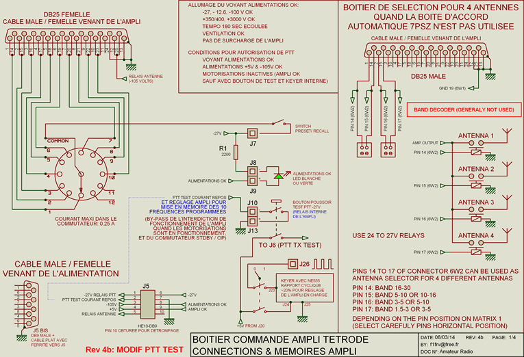
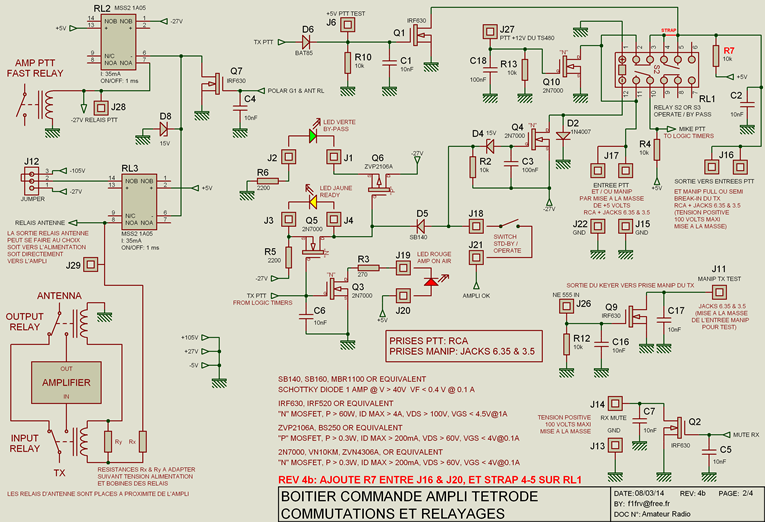
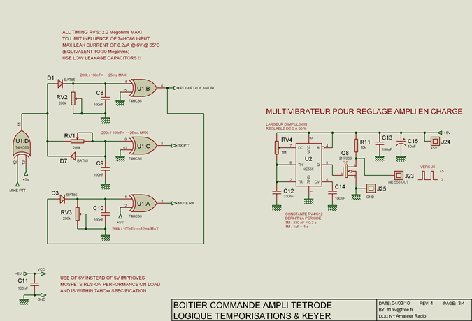
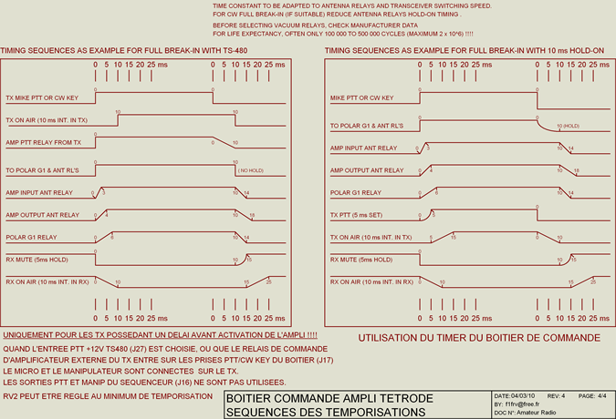
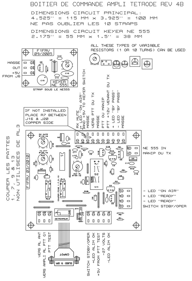
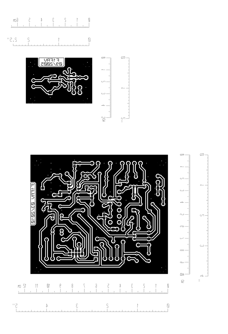
The remote command box for this amplifier
You can see some pictures (click to enlarge)
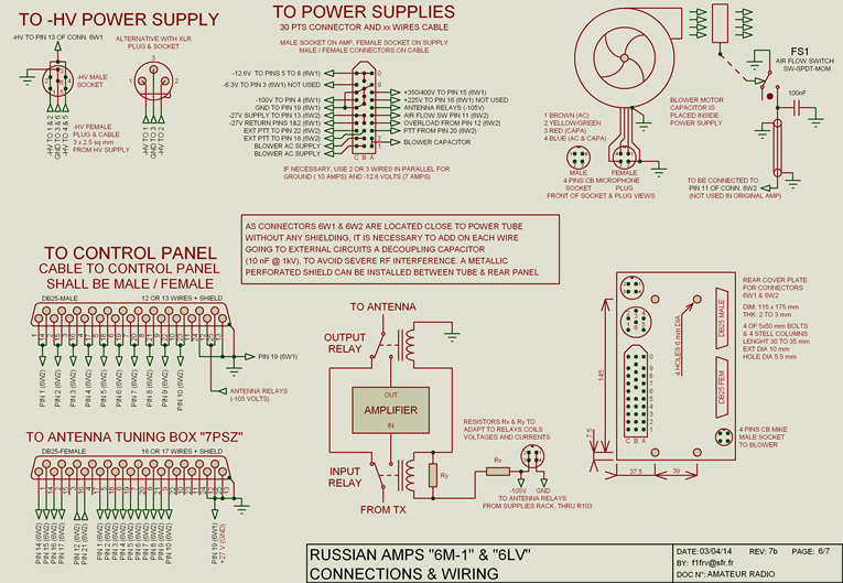
Connectors 6W1 & 6W2 decoupling, remote control box front and rear
Rear connectors to supplies & control box
Output relay for 2 kW max, input relay S2, with 6 dB attenuator
Output relay for 5 kW max with DIN 7x16 connectors
Wideband input circuit, wires shielding added behind connectors 6W1 & 2
Measurements: SWR at amplifier input, SWR in by-pass, relay insulation
Download schematic diagrams (rebuild & originals) and PCB's here:
R-140 amp and control box: schematics & PCB
Internal link to output pi network improvements
Internal link to tetrode power supplies & auxiliary circuits
Internal link to high voltage power supply
Internal link to replacement of GU-43b by GU-78b to increase power
Internal link to "7PSZ" R-140 antenna tuner
Links to other R-140 pages |
(english translation) |
Special thanks to some hams, who helped me to find technical documentations:
Pavel Vachal OK1DX, Milan Rusky OK1MR, Ludek Odehnal OK2ZC, and www.cqham.ru.
Nota. Some other original R-140 schematics and documents are available. In case of need, go to R-140 main page.
Dominique - f1frv@sfr.fr
 OR
OR 


