Tetrode linear amplifier boards by F1FRV |
Pour traduction de la page en français cliquer sur drapeau français
![]() - -
- - ![]() - -
- - ![]() - -
- - ![]() - -
- - ![]() - -
- - ![]()
* Rev 0: December 2005 *
* Rev 1: May 2007 *
* Rev 2: May 2010: Added low ripple G2 supply *
* Rev 3: November 2010: Global update, except heater supply *
* Rev 5: August 2014. New boards design *
* Rev 5a: March 2015. Added 19" 3U rack example & G2 simple meter *
* Rev 6: October 2018. Circuits G1 & G2 for very high power tubes *
* July 2019. Added info about new central 0 meters *
* August 2021. Small improvements in single side PCBs *
* December 2021. Professionaly made PCBs for G1 & G2 availables *
* January 2022. Updated G2 card up-to 1500 V *
* December 2023. G1 adaptation & 10 or 12 bands Low pass filters *
![]() * june 2025. New set of boards & automatic translations *
* june 2025. New set of boards & automatic translations *
Aide technique (Français) Droits d'auteur (Copyrights)
Tetrodes are more difficult to use than triodes. This is due to additional supplies and safety interlocks. Nevertheless, they are ONLY interresting for powers >1.5 to 2 kW. If you dont have the ~150 or 200 Watts necessary to drive a pair of GS-35b to ~3.5 to 4 kW output, you can use a GU-78b, which needs only ~50 Watts for 5 kW output. Small tetrodes are not at all interresting for economical and works necessary time reasons. For "BIG" tetrodes, if you need a good HV transfo, see HERE .
A good point for SOME tetrodes used in decametric bands amplifiers: A wideband grid 1 input circuit (see later on this page) is very efficient and simpler than a cathode driven triode with bands switched input circuits, but, this is simple ONLY for tubes which needs only less than ~70 Volts grid swing on 50 Ohms (~100 Watts) for full power like 4CX-1000, 4CX-1500, 4CX-3000, GU-43B or GU-78B.
For bigger tubes like 4CX-5000 or 4CX-10000, an impedance adaptation (200 to 600 Ohms) and a 10 or 12 bands low pass filters are needed to reduce drive power ...
This page is only for those who dont want to build a wiring mess (Bamako engineering, dixit Rémy l'abbé J)
, without schematics, and without enough safety for them and equipment, but accept to pay what is minimum necessary (only a few among hams). No major technical changes between this one and the old revisions (they worked), except some layout arrangements, which removed mains AC voltage from logic board, easier wiring to front panel PCB (LEDs and switches) with flat ribbon cable and IDC instead of terminal screwed blocks.
These NEW cards, replaces the old 2005/2007/2013 boards. They performs all functions required by a power tetrode amplifier (except amplification and HV supply).
The main features are:
- Switched and fused mains outlets for heaters, auxiliary and antenna relays power supplies.
- Tubes heaters “soft start” to limit inrush current and extend tubes life.
- Start-up timer for cathode heating ~ 3 minutes before being ready to operate. This is not necessary for tubes with heater filament used as cathode, eg. 8166/4-1000A, QB4-1100, QB5-1750, QBL5-3500, GU-5B etc.
- PTT logic timers to avoid “hot switching” and perform controled sequences during transmit-receive operations. This circuit includes also RX preamplifier control.
- Blower delayed stop, after amplifier switch off ~ 3 minutes, to evacuate accumulated heat in tube. Blower protection fuses for operator safety, as blower is not switched by amplifier off switch.
- All board inlets and outlets by screwed terminal blocks and IDCs with flat ribbon cables.
- Grid 1 PTT control via fast switching relay ( 7/3 ms ).
- Grid 1 adjustable bias voltage shunt regulation circuit, with protection fuse.
- Grid 2 adjustable shunt power supply, with high voltage power MOSFET or IGBT. Trip circuit in case of current excess, or loss of G2 voltage.
- Sequencer for application of G2 voltage AFTER and WITH high voltage (HV MUST be present).
- Anode current meter, High voltage meter.
- RF circuitry, input and output matching networks are not fully described here, as a lot of descriptions are available on the web (and elsewhere in my web pages). These boards can be used with all tetrodes, from the smallest (not very interresting) to the more powerful (more interresting).
Printed circuit boards used in this design:
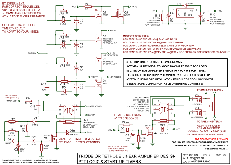
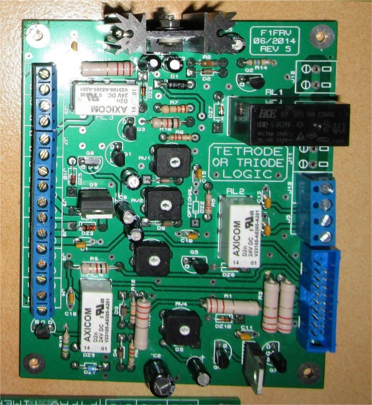
- Logic board, professionaly made PCB, dual side, with plated thru holes, serigraphy and resist varnishes. It includes cathode start-up timer, safety chain, PTT logic timer, tube soft start heater.
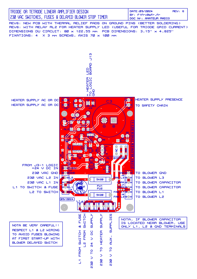
- Blower stop timer, professionaly made PCB, dual side, with plated thru holes, serigraphy and resist varnishes. It includes AC 230 V mains and blower fuses, shut-off blower timer, tube heater voltage detection.
- Front panel LEDs and switches, professionaly made PCB, dual side, with plated thru holes, serigraphy and resist varnishes. Connections to logic board by 20 wires flat ribbon cable and IDCs.
- Grid 1 shunt regulated supply, and G1 voltage detection. professionaly made PCB, single side, serigraphy and resist varnish. Separate voltages for grid blocking and grid adjustable bias.
- Sequencer for application of HV and G2 voltages, in the right and safe way for the tube, when all safety devices are OK. High voltage detection. IP & HV meters.
- Grid 2 shunt regulated supply, with power MOSFET or IGBT. professionaly made PCB, single side, serigraphy and resist varnish. G2 voltage detection and overcurrent trip relay. Tested voltage stability is better than 1 V between 0 and +/- 100 mA.
- Professionaly made PCBs are availables, see HERE.
OPTIONAL: A choke inductor for G1 & G2 very low ripple supplies can be used.
Some EXCEL and PDF files are included in the downloadable files, to help you in your own design.
Some simulations of very good, good, bad and very bad grid supplies are available HERE . Dont laugh, some people, in our 21th century, still never heard about tetrodes negative G2 current and shunt supplies.
NOTA: As 24V DC supply is with negative at ground, be careful if you want to use these boards with R-140
russian amplifiers.
Not so bad and versatile …. isn’t it ???
All values are given as practical example. This design can be easily adapted to any tubes.
- If needed, change the values of timings in accordance with your transceiver and antenna relays. An EXCEL calculation sheet is in the downloads, to help you. Calculated timings are not extremely accurate, as FETs gates voltages for conduction are depending of a lot of parametres, and capacitors leakage current is not taken into account. Do not use resistors higher than ~ 2 Megohms, to limit influence of FET gate and capacitor impedances.
- Change heater “soft start” resistor (R "x") value according to your tube(s) heater data. Heater voltage can be either AC, or, better, DC with low weight and low cost switching regulated supplies. Heater soft start: Calculate R "x" resistor according to Ohm's law (if you heard about it...), for nominal current of heater under short circuit. As example, for heater 27 V @ ~ 4 Amps (GU-78b), resistor shall be ~ 6.8 Ohms. This limits inrush heater current to ~ 4 Amps, (instead of more than 50 Amps), and gives ~ half nominal heater voltage and current to the tube after a few seconds. Power of R "x", for less than 10 seconds of service, can be reducced to ~ 1/2 of what is calculated (in this case, 25 W is OK). For heater current higher than 16 Amps, RL1 shall drive an external power relay.
For tubes like TH293 which needs extended time (>1 minute) at half heater voltage, timing capacitor C5 must be modified for longer time delay. In this case, " Rx" shall accept full heater half power without burning.
All components are available at Radiospares, Farnell, or in Ebay chinese low cost suppliers. Bill of materials are supplied.
For information: to build an amplifier, total cost for necessary PCBs and related components is ~ 200 to 300 Euros. Its why small tubes are not not very interresting ...
Schematic diagrams & layouts
Part 1: Logic card
The logic card, like previous revision, can be used, either for tetrode, SSPA, or for triode amplifiers.
If you think that safety is excessive for you in this design, remove all safeties you dont want, at your own risks ...
Old revision 5
Professionaly made PCBs see HERE
Part 2: Blower timer card
The blower timer card can be used, either for tetrode, SSPA, or for triode amplifiers. Mains (230 V or else) AC voltage is present only on this board. There is also on this board a circuit for heater voltage (AC or DC) detection to front panel LED (via logic board). A special version for other application, with 13.8 V supply instead of 24 V has been made. Documentation is in the downloads.
Old revision 5
Part 3: Grid 2 card
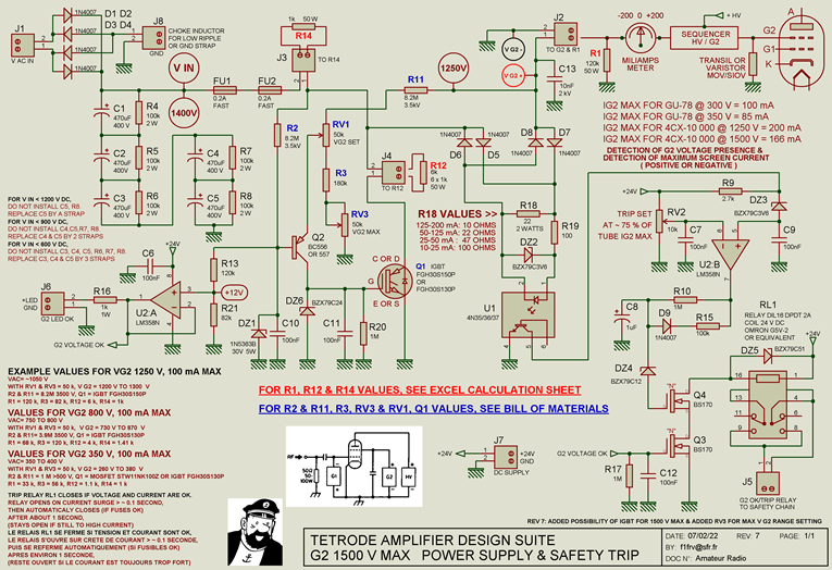
This improved design, can use a choke input rectifier ( not mandatory ) for low ripple, to improve IMD. Without choke inductor, replace it by a strap (or a resistor in case of too high AC voltage transformer for your need, this is also a way to reduce DC rectified voltage). A power MOSFET or an IGBT is used in the shunt supply. An excel sheet is supplied to calculate parameters. A trip adjustable circuit protect the tube from destruction by G2 excess current. A detection circuit, insulated by opto coupler, watches G2 voltage presence and acceptable current, to send information into safety chain and front pannel. Old circuit rev 5 was made for tubes like GU-43b, 4CX-1500 or GU-78b, adapted to G2 regulated voltages up-to 500 Volts. Circuit revision 6b1, was made ALSO for big tubes like 4CX-5000 or 10000, GU-35b, or QBL5-3500, and adapted to G2 regulated voltage up-to 1000 V.
Circuit revision 7
This arrangement is made to use central 0 meters which were hard to find. NOW, since 2019, we can find them in Asia at correct prices (~5 Euros) some 85C1 meters, for ranges -100_ 0 _+100 mA, -200_ 0 _+200 mA, or -30_ 0 _+30 mA. Download 85C1 data.
Part 4: Grid 1 circuit
These circuits are made for grounded cathode designs. A new G1 voltage detection system, more versatile, and less heat generating is used. Revision 5a was made for tubes like GU-43b, 4CX-1500, GU-78b, it uses revision 6a PCB and a few straps in lieu of non used components. G1 DC rectified voltage is up-to ~300 V, for shunt regulated tube blocking voltage up-to 250 V. Click here for G1 150 V simulation results . Revision 6a and more recent, are made ALSO for big tubes (4CX-5000 or 10000, GU-35b, QBL5-3500) with G1 DC rectified voltage up-to 600 V, for shunt regulated tube blocking voltage up-to 500 V. Click here for G1 360 V simulation results. Click here for 4CX-10000 G1 simulations.
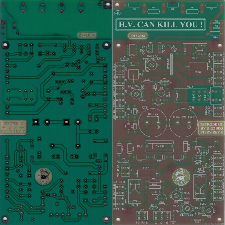
Revision 8
A safety circuit is included to avoid having G2 voltage present with no high voltage on anode. This would destroy tube in case of transmission in this configuration. The HV relay B1B is optional.
A high voltage detection circuit is provided for front panel indication and insertion into safety chain. Five high voltage resistors (3500 V each) are used, 3.3 M up-to 4.5 kV, 6.8 or 8.2 M up-to 7 kV. An insulating protection plate (plexiglass) over the high voltage components is mandatory to avoid LETHAL accidental hand contact.
BEWARE !!! HV CAN KILL YOU !!!
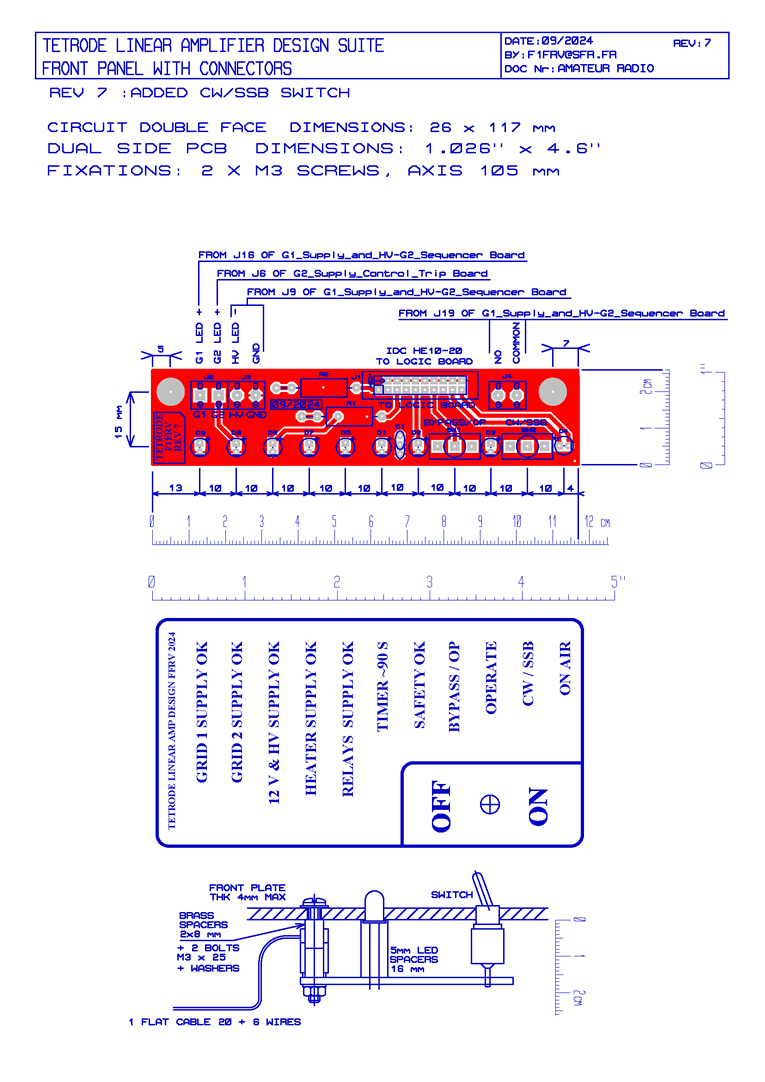
Part 5: Front panel card
This design minimizes wiring works, in using flat ribbon cable and insulation displacement connector (IDC) HE10-20 standard, in lieu of a lot of screwed terminal blocs. All important monitoring parameters are visualised. A dual side PCB with metallised thru holes, resist varnishes & silkscreen is available.
New PCB dual side
Old PCB single side
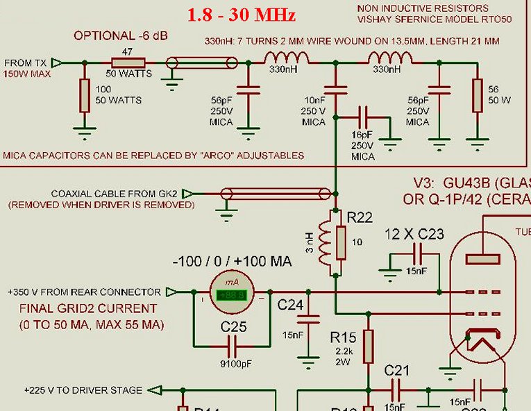
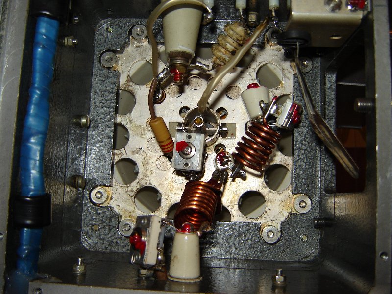
For information, a typical wideband HF input circuit.
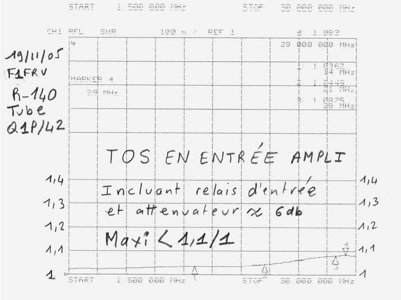
R-140 Russian amplifier input
For information, example of layout in 19" rack
Download May 2025 new boards Bill of materials & documentation
Download boards before may 2025 rev 5, 6 & 7 Bill of materials & documentation


Download critical components documentation & datasheets
Download choke inductances documentation
Download layout in 19" rack documentation
Download tetrode RF input circuit design
Download VERY OLD tetrode boards documentation
Click here for some pictures of the previous cards
************************
Internal link to high voltage power supply
Internal link to BIG HV transformers
Internal link to PI network design
For now,

Enjoy !!!!
![]() Dominique - f1frv@sfr.fr
Dominique - f1frv@sfr.fr  OR
OR